background image

4.3  HOST (DTE) CONNECTION

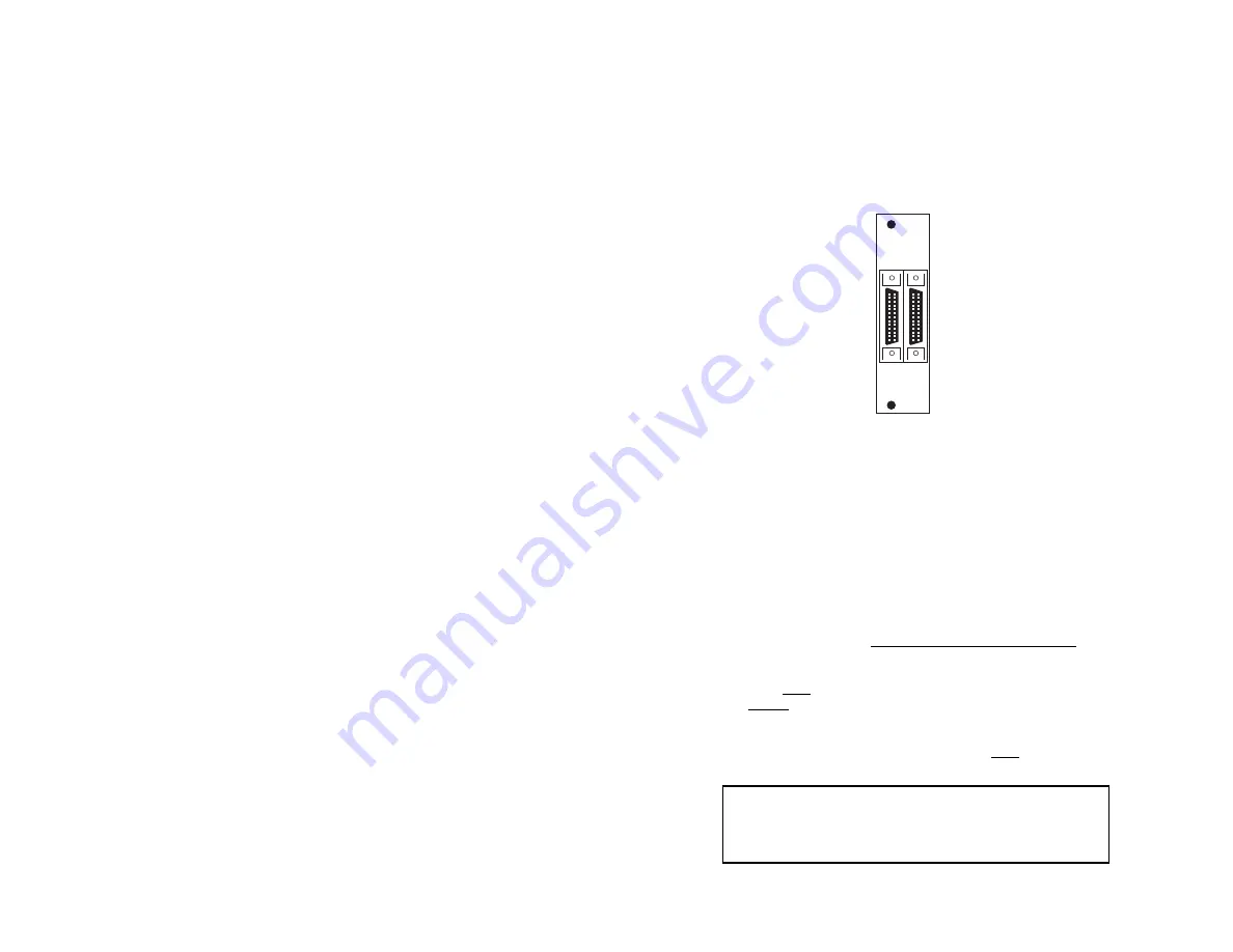
The Model 1206RC rear card has two UD-26 connectors, labeled

“A1” and “B1” (see figure 7, below).  These correspond to host (DTE)
connection Port A and Port B, as discussed in Section 3.0.

To connect X.21 host (DTE) devices A and B to the Model 1206RC,

follow these instructions:

1. Configure the Model 1206RC for your specific application according

to the instructions in 

Section 3.0

of this manual.

2. Connect host devices A and B to the Model 1206RC using multipair

adapter cables (see 

Appendix B

for a list of custom adapter cables

available from Patton Electronics).  Observe the following
conditions when making connections :

a)

Each multipair cable must not exceed 150 feet in length.

b)

If external clock is used, the host (DTE) device supplying the 
clock must be connected to Port A.  The Model 1206RC 
cannot receive an external clock on Port B (see Section 3.0   
for configuration details).

c)

If receive clock is used on Port B,  Port A must supply an 
external clock (see Section 3.0 for configuration details).

10

Switching the Power Supply On and Off

The power supply on/off switch is located on the front panel.  When

plugged in and switched on, a red front panel LED will glow.  Since the
Model 1000R16 is a “hot swappable” rack, 

it is not necessary for any

cards to be installed before switching on the power supply

.  The power

supply may be switched off at any time without harming the installed
cards.

NOTE:  

Please refer to the Model 1000RP Series User Manual 

AC 

and DC Rack Mount Power Supplie

s for fuse and power card 

replacement information.

4.2  INSTALLING THE MODEL 1206RC INTO THE CHASSIS

The Model 1206RC is comprised of a front card and a rear card.

The two cards meet inside the rack chassis and plug into each other by
way of mating 50 pin card edge connectors.  Use the following steps as
a guideline for installing each Model 1206RC into the rack chassis:

1.

Slide the rear card into the back of the chassis along the metal
rails provided.

2.

Secure the rear card using the metal screws provided.

3.

Slide the card into the front of the chassis.  It should meet the
rear card when it’s almost all the way into the chassis.

4.

Push the front card 

gently

into the card-edge receptacle of the

rear card.  It should “click” into place.

5.

Secure the front card using the thumb screws. 

NOTE:  

Since the Model 1000R16 chassis allows “hot swapping” 

of cards, it is 

not necessary to power down

the rack when you install

or remove a Model 1206RC.

9

Figure 7.

Model 1206RC rear interface card, showing connectors 

A1  B1

Notice!

Any terminal cable connected to the Model

1206RC must be shielded cable, and the outer shield must
be 360 degree bonded–at both ends–to a metal or
metalized backshell.

Summary of Contents for 1206RC

Page 1: ...o tell us how you like this product and how we can meet your product needs today and in the future Web http www patton com Sales E mail sales patton com Support E mail support patton com Phone Sales 3...

Page 2: ...ot occur in a particular installation If the Model 1206RC does cause interference to radio or television reception which can be determined by turning the power off or removing the card the user is enc...

Page 3: ...ot occur in a particular installation If the Model 1206RC does cause interference to radio or television reception which can be determined by turning the power off or removing the card the user is enc...

Page 4: ...s arise during installation or use of this product please do not hesitate to contact Patton Electronics Technical Support at 301 975 1007 support patton com or http www patton com 2 1 FEATURES X 21 op...

Page 5: ...s arise during installation or use of this product please do not hesitate to contact Patton Electronics Technical Support at 301 975 1007 support patton com or http www patton com 2 1 FEATURES X 21 op...

Page 6: ...setting 6 S1 through S3 Data Rate Setting Switches S1 through S3 are set in combination to determine the synchronous data rate for the Model 1206RC Switch S4 is not active S1 S2 S3 S4 Setting Off Off...

Page 7: ...setting 6 S1 through S3 Data Rate Setting Switches S1 through S3 are set in combination to determine the synchronous data rate for the Model 1206RC Switch S4 is not active S1 S2 S3 S4 Setting Off Off...

Page 8: ...by thumb screws and the rear card by conventional metal screws 8 3 4 REAR CARD CONFIGURATION The rear interface card for the Model 1206RC is equipped with two female UD 26 connectors one for each DTE...

Page 9: ...by thumb screws and the rear card by conventional metal screws 8 3 4 REAR CARD CONFIGURATION The rear interface card for the Model 1206RC is equipped with two female UD 26 connectors one for each DTE...

Page 10: ...necessary for any cards to be installed before switching on the power supply The power supply may be switched off at any time without harming the installed cards NOTE Please refer to the Model 1000RP...

Page 11: ...necessary for any cards to be installed before switching on the power supply The power supply may be switched off at any time without harming the installed cards NOTE Please refer to the Model 1000RP...

Page 12: ...cribes the LED status monitors and power up procedure 5 1 LED STATUS MONITORS The Model 1206RC features 9 front panel status LEDs that indicate the condition of the Model 1206RC and the two ports A B...

Page 13: ...cribes the LED status monitors and power up procedure 5 1 LED STATUS MONITORS The Model 1206RC features 9 front panel status LEDs that indicate the condition of the Model 1206RC and the two ports A B...

Page 14: ...d 0805JAP Japan Power Cord 0805SW Switzerland Power Cord 0516FPB1 Single Width Blank Front Panel 0516FPB4 4 Wide Blank Front Panel 0516RPB1 Single Width Blank Rear Panel 0516RPB4 4 Wide Blank Rear Pan...

Page 15: ...d 0805JAP Japan Power Cord 0805SW Switzerland Power Cord 0516FPB1 Single Width Blank Front Panel 0516FPB4 4 Wide Blank Front Panel 0516RPB1 Single Width Blank Rear Panel 0516RPB4 4 Wide Blank Rear Pan...

Page 16: ...16 Transmit Clock TC 15 Transmit Data TD 14 15 Notes __________________________________________ __________________________________________ __________________________________________ _________________...

Page 17: ...16 Transmit Clock TC 15 Transmit Data TD 14 15 Notes __________________________________________ __________________________________________ __________________________________________ _________________...

Page 18: ..._____________ __________________________________________ __________________________________________ Notes __________________________________________ __________________________________________ ________...

Page 19: ..._____________ __________________________________________ __________________________________________ Notes __________________________________________ __________________________________________ ________...

Page 20: ...l us how you like this product and how we can meet your product needs today and in the future Web http www patton com Sales E mail sales patton com Support E mail support patton com Phone Sales 301 97...

Reviews: