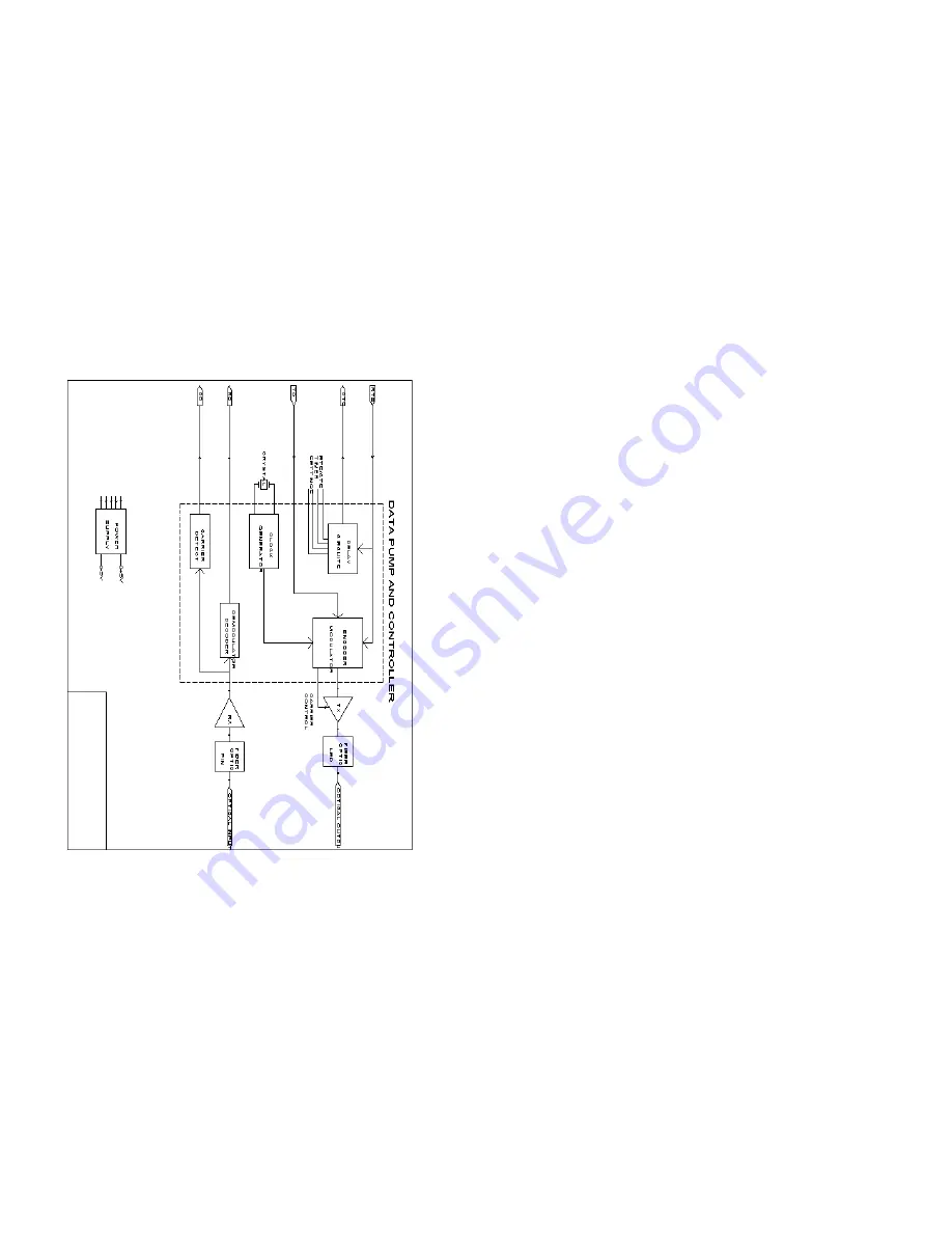
APPENDIX D
BLOCK DIAGRAM
Copyright ©
Patton Electronics Company
All Rights Reserved
MODEL
1
140RC
B
LOCK
D
IAGRAM
21
Page 1: ...this product and how we can meet your product needs today and in the future Web http www patton com Sales E mail sales patton com Support E mail support patton com Phone Sales 301 975 1000 Phone Supp...
Page 2: ...ar installation If the Model 1140RC does cause interference to radio or television reception which can be determined by turning the power off or removing the card the user is encouraged to try to corr...
Page 3: ...Diagnostics Mounts in Patton s 16 Card Rack Chassis Compatible with the Patton Model 1140 self powered modem Immune to RFI EMI noise ground loops and transient surges Easily accessible configuration j...
Page 4: ...S1 The DIP switches on S1 set data rate clock source async sync mode and carrier control method The default settings are summarized in the table below Following the table is a description of all poss...
Page 5: ...S2 set word length extended signaling rate RTS CTS delay and V 52 and V 54 diagnostic test The default settings are summarized in the table below Following the table is a description of all possible S...
Page 6: ...card slots plus its own power supply Measuring only 3 5 high the 1000R16 is designed to occupy only 2U in a 19 rack Sturdy front handles allow the 1000R16 to be extracted and transported conveniently...
Page 7: ...e installed before switching on the power supply The power supply may be switched off at any time without harming the installed cards NOTE Please refer to the Model 1000RP Series User Manual AC and DC...
Page 8: ...pin 8 The Test LED glows when either the Local Analog Loopback LAL or Remote Digital Loopback RDL V 54 test mode is initiated The Error LED blinks when an error is detected by the V 52 diagnostics 5 2...
Page 9: ...nt If you still have errors call Patton Technical Support at 301 975 1007 5 3 2 REMOTE DIGITAL LOOPBACK RDL The Remote Digital Loopback RDL test checks the performance of both the local and remote Mod...
Page 10: ...ng Weight 2 oz Dimensions 0 95 W x 3 1 H x 5 4 L 17 18 1 Locate the lower of the two toggle switches on the front panel of the Model 1140RC and move it to the right This will activate the V 52 BER tes...
Page 11: ...0805EUR European Power Cord CEE 7 0805UK United Kingdom Power Cord 0805AUS Australia New Zealand Power Cord 0805DEN Denmark Power Cord 0805FR France Belgium Power Cord 0805IN India Power Cord 0805IS I...
Page 12: ...APPENDIX D BLOCK DIAGRAM Copyright Patton Electronics Company All Rights Reserved MODEL 1140RC B LOCK D IAGRAM 21...