USER
MANUAL
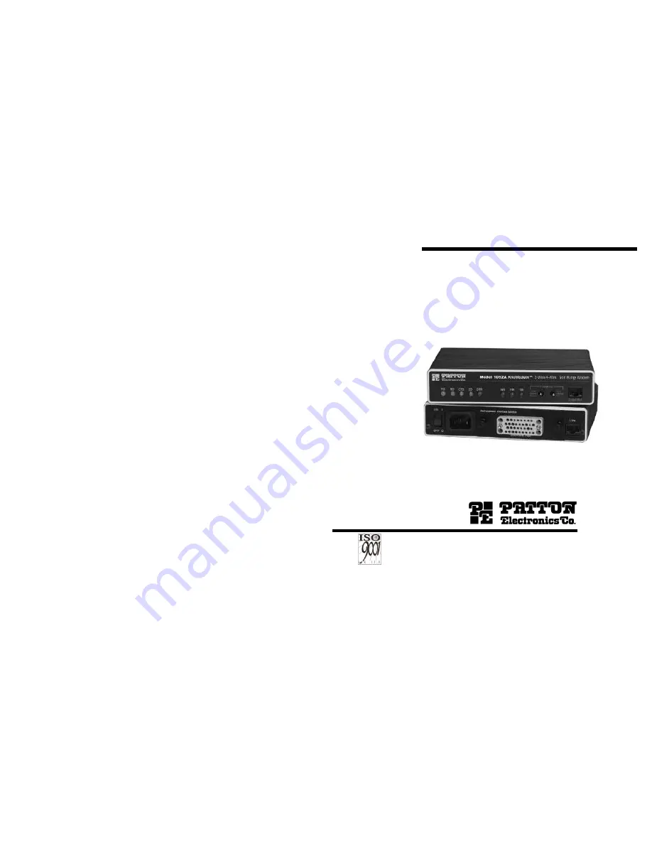
MODEL 1092A
High Speed, 2-Wire/4-Wire,Sync & Async Short Range Modem
Part# 07M1092A-EDoc# 033031UDRevised 03/29/00
SALES OFFICE(301)975-1000TECHNICAL SUPPORT(301)975-1007http://www.patton.com
An ISO-9001
Certified
Company
Page 1: ...DEL 1092A High Speed 2 Wire 4 Wire Sync Async Short Range Modem Part 07M1092A E Doc 033031UD Revised 03 29 00 SALES OFFICE 301 975 1000 TECHNICAL SUPPORT 301 975 1007 http www patton com An ISO 9001 Certified Company ...
Page 2: ...condition shall Patton Electronics be liable for any damages incurred by the use of this product These damages include but are not limited to the following lost profits lost savings and incidental or consequential damages arising from the use of or inability to use this product Patton Electronics specifically disclaims all other warranties expressed or implied and the installation or use of this p...
Page 3: ...twisted pair 2 or 4 Wires Point to point distances up to 11 miles 17 6Km Remote digital loopback local line loopback diagnostics Internal external or receive recovered clocking options LED indicators for TD RD CTS CD DTR TM ER and NS Standard Gas Tube Surge Protection Made in the U S A 2 2 DESCRIPTION The Patton Electronics Model 1092A KiloModem 2W 4WTM baseband modem allows synchronous or asynchr...
Page 4: ...f eight DIP switches which allow configuration of the unit to a wide variety of applications This section describes switch locations and explains all possible configurations 3 1 CONFIGURING THE HARDWARE DIP SWITCHES The Model 1092A uses a unique set of 16 external mini DIP switches that allow configuration to a wide range of applications The 16 external switches are grouped into two eight switch s...
Page 5: ...n Reserved Reserved On Off On Reserved Reserved Off Off On 19 2 kbps Reserved Possible Bit Rate Settings Switch S1 1 S1 2 and S2 1 8 Switch S1 3 Data Set Ready During Line Loopback Test Use Switch S1 3 to control the behavior of the DSR signal at the EIA interface during the line loopback test S 3 Setting On DSR is on during local line loop Off DSR is off during local line loop Switches S1 4 Manag...
Page 6: ...2 SUMMARY TABLE Position Function Factory Default S2 1 Data Rate Off S2 2 Front Panel Switch Enable Off Enable S2 3 Response to LAL from DTE Off Disabled S2 4 2 Wire 4 Wire Off 2 Wire S2 5 Not Assigned Off S2 6 Response to RDL from DTE On Enabled S2 7 Not Assigned Off S2 8 Not Assigned Off 10 Switch S2 3 Response to Local Line Loop Requests from DTE Use Switch S2 3 to enable Local Line Loopback co...
Page 7: ...wered on the control port will send out this message Model 1092A Software version x xx Patton Electronics Copyright C 2000 5 Press ESC on the terminal 6 The 1092A will then display the MAIN MENU screen You may configure the LOCAL Model 1092A from this screen Important To make a selection from any menu enter the option number To exit any menu without making a selection or to return to the previous ...
Page 8: ...inally select MAIN MENU Option 8 to save the changes SOFTWARE 14 MAIN MENU Option 4 Setup Software Configuration Select Option 4 to edit the software configuration of the Model 1092A To save changes after editing the software configuration select MAIN MENU Option 5 then select Use Software Switches and then select MAIN MENU Option 8 1 DTE Rate Select Option 1 in the SOFTWARE CONFIGURATION menu to ...
Page 9: ...ster Clock either internal or external and the other must be Slaved to the Receive Clock 16 4 DSR During Local Line Loop Select Option 4 in the SOFTWARE CONFIGURATION to configure the behavior of the local Data Set Ready DSR signal during the Local Line Loop test mode below 5 Response to Remote Digital Loop Select Option 5 in the SOFTWARE CONFIGURATION Menu to instruct the Model 1092A to either re...
Page 10: ...on 1 4 Wire Mode 2 2 Wire Mode MAIN MENU Option 6 Display Modem Status Select Option 6 from MAIN MENU to display the Modem Status below Press the space bar on the keyboard to update and redisplay the screen NOTE Valid Model 1092A Handshake Statuses are listed below 1 Handshaking This status occurs when the 1092A is in the process of establishing a link with another 1092A 2 Data Mode This status oc...
Page 11: ... Menu Press the space bar to update and redisplay the status 20 4 0 INSTALLATION Once the Model 1092A is properly configured it is ready to connect to the twisted pair interface to the serial port and to the power source This section tells you how to make these connections 4 1 CONNECTING THE TWISTED PAIR INTERFACE The Model 1092A supports communication between two DTE devices at distances to 5 mil...
Page 12: ...particular version of the Model 1092A it should be shipped to you with the appropriate QuikConnect Module already installed If you need to install a different QuikConnect Module follow these steps Removing the Existing QuikConnect Module 1 Turn the power switch off Leave the power cord plugged into a grounded outlet to keep the unit grounded 2 Loosen the two thumbscrews on the module by turning th...
Page 13: ...Pin out requirements for null modem applications vary widely between manufacturers If you have any questions about a specific application contact Patton Electronics Technical Support 24 4 2 4 Configuring the X 21 QuikConnect Module The serial port on the X 21 QuikConnect Module is default wired as a DCE but may be switched to a DTE This is done by reversing the orientation of the DCE DTE strap as ...
Page 14: ...er switch 5 2 LED STATUS MONITORS The Model 1092A features eight front panel LEDs that monitor power the DTE signals network connection and test modes Figure 6 below shows the front panel location of each LED Following Figure 6 is a description of each LEDs function TD RD Glows yellow to indicate an idle condition of Binary 1 data on the respective terminal interface signals Green indicates Binary...
Page 15: ...t indicates no faults but the data terminal indicates a fault follow the manufacturer s checkout procedures for the data terminal Also check the interface cable between the terminal and the Model 1092A Figure 7 Local Line Loopback LLB initiated 27 5 3 2 Remote Digital Loopback RDL The Remote Digital Loopback RDL test checks the performance of both the local and remote Model 1092As and the communic...
Page 16: ...ir Clocking Internal external or receive loopback Interface Modules EIA RS 232 ITU T V 24 RS 232 530 ITU T V 35 ITU T X 21 64k G 703 10BaseT Ethernet and Voice Data Data Rates Synchronous 19 2 32 56 64 128 kbps Asynchronous0 38 4 kbps Diagnostics V 52 compliant bit error rate pattern 511 511E pattern generator and detector with error injection mode Local Line Loopback and Remote Digital Loopback a...
Page 17: ...srael Power Cord 0805JAP Japan Power Cord 0805SW Switzerland Power Cord 31 APPENDIX C PATTON ELECTRONICS MODEL 1092A INTERFACE PIN ASSIGNMENT RS 232 RS 530 Interface Pin Description DB 25 Female Connector DCE Configuration Pin Signal 1 FG Frame Ground 2 TD Transmit Data 3 RD Receive Data 4 RTS Request to Send 5 CTS Clear to Send 6 DSR Data Set Ready 7 SGND Signal Ground 8 CD Carrier Detect 9 RC Re...
Page 18: ...a B T RD Receive Data B U XTC External Transmit Clock V RC Receive Timing W XTC External Transmit Clock X RC Receive Timing Y TC Transmit Timing A AA TC Transmit Timing B 34 APPENDIX C PATTON ELECTRONICS MODEL 1092A INTERFACE PIN ASSIGNMENT Continued X 21 Interface DB 15 Female Connector DTE DCE Configuration Pin Signal 1 Frame Ground 2 T Transmit Data A 3 C Control A 4 R Receive Data A 5 I Indica...
Page 19: ...ster the other unit as Slave MASTER UNIT SETTINGS S1 1 ON S1 2 OFF S1 3 ON S1 4 and 5 OFF S1 6 and 7 ON S1 8 ON S2 1 2 and 3 OFF S2 4 ON 4 wire operation OFF 2 wire operation S2 5 OFF S2 6 7 and 8 ON SLAVE UNIT SETTINGS S1 1 ON S1 2 OFF S1 3 ON S1 4 and 5 OFF S1 6 ON S1 7 OFF S1 8 ON Switch S2 settings are the same as the MASTER UNIT 3 Connect the twisted pair circuit between the model 1092A s tur...