background image

RJ-45

SIGNAL

PIN#

COLOR

COLOR PIN#

SIGNAL

GND

2

Orange.............Brown

7

GND

RCV-

3

Black ................Green

5

XMT-

XMT+

4

Red ..................Yellow

6

RCV+

XMT-

5

Green...............Black

3

RCV-

RCV+

6

Yellow ..............Red

4

XMT+

GND

7

Brown ..............Orange

2

GND

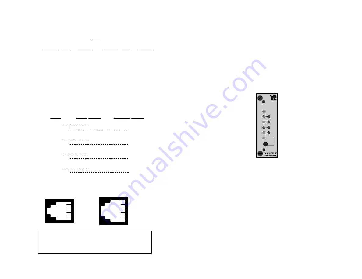
4.4.2  Multipoint Twisted Pair Connection

Figure 11 (below) shows how to wire two-pair cables properly for a

Model 1060RC star topology.  

5.0  OPERATION

Once you have configured each Model 1060RC and connected the

cables, you are ready to operate the units.  Section 5.0 describes the
LED status monitors, the power-up procedure and the use of the built-in
loopback test modes.

5.1  LED STATUS MONITORS

The Model 1060RC features ten front panel status LEDs that

indicate the condition of the modem and communication link.  Figure 12
(below) shows the relative front panel positions of the LEDs.  Following
figure 12 is a description of each LED's function.

Power

glows green when power is applied to the Model 
1060RC front card.

TD & RD

The green "TD" and "RD" indicators blink to show 
positive state data activity.  The red "TD" and "RD" 
indicators blink to show negative state data activity.  
Solid red indicates a connection in an idle state.

Cntrl

in

and

glow red to show that either control signal is off.  

Cntrl

out

Glow green to show that either control signal is on.
When the 1060RC is connected to a DTE, Control In 
will glow green for a positive polarity on the Control 
Input signal.  Control Out will glow green for an 
incoming signal from the line.

Test

glows green when the loopback test modes are 
activated.

15

16

Figure 12.

The Model 1060RC front panel, showing LED positions

Model 1060RC

Power

TD

RD

Cntrl

Out

Test

Cntrl

In

Notice!

Any modular twisted pair cable connected to

the Model 1060RC must be shielded cable, and the outer
shield must be properly terminated to a shielded modular
plug on both ends of the cable.

HOST

FIRST SLAVE

SECOND SLAVE

XMT+

RCV+

RCV+

XMT-

RCV-

RCV-

RCV+

XMT+

XMT+

RCV-

XMT-

XMT-

Figure 11.

Two-pair star wiring for Model 1060RC host and slaves

1 - Blue

2 - Orange

3 - Black

4 - Red

5 - Green

6 - Yellow

7 - Brown

8 - Slate

1 - Blue

2 - Yellow

3 - Green

4 - Red

5 - Black

6 - White

RJ-11

RJ-45

Summary of Contents for 1060RC

Page 1: ...owered Asynchronous Short Range Modem Rack Mount Card SALES OFFICE 301 975 1000 TECHNICAL SUPPORT 301 975 1007 http www patton com Part 07M1060RC B Doc 058021U Rev C Revised 1 23 08 C E R T I F I E D...

Page 2: ...ar installation If the Model 1060RC does cause interference to radio or television reception which can be determined by turning the power off or removing the card the user is encouraged to try to corr...

Page 3: ...ar installation If the Model 1060RC does cause interference to radio or television reception which can be determined by turning the power off or removing the card the user is encouraged to try to corr...

Page 4: ...tection Supports distances up to 14 miles 22 5 km Mounts in Patton s 16 card rack chassis Bi state LED indicators Point to point or multipoint operation Local and remote loopback test modes Hardware a...

Page 5: ...tection Supports distances up to 14 miles 22 5 km Mounts in Patton s 16 card rack chassis Bi state LED indicators Point to point or multipoint operation Local and remote loopback test modes Hardware a...

Page 6: ...ll not need an in depth knowledge of the Model 1060RC s capabilities to get up and running The following quick set up DIP switch configurations cover most Model 1060RC operating environments 3 2 1 Poi...

Page 7: ...ll not need an in depth knowledge of the Model 1060RC s capabilities to get up and running The following quick set up DIP switch configurations cover most Model 1060RC operating environments 3 2 1 Poi...

Page 8: ...describe the strap locations and possible settings for each rear card 3 4 1 DB 25 RJ 11 DB 25 RJ 45 Strap Settings Figure 5 below shows strap locations for the Model 1000RCM12511 DB 25 RJ 11 and the...

Page 9: ...describe the strap locations and possible settings for each rear card 3 4 1 DB 25 RJ 11 DB 25 RJ 45 Strap Settings Figure 5 below shows strap locations for the Model 1000RCM12511 DB 25 RJ 11 and the...

Page 10: ...RJ 11 RJ 45 RJ 45 Strap Settings Figure 8 opposite page shows strap locations for the Model 1000RCM1D11 RJ 45 RJ 11 and the Model 1000RCM1D45 RJ 45 RJ 45 rear cards These straps determine various gro...

Page 11: ...RJ 11 RJ 45 RJ 45 Strap Settings Figure 8 opposite page shows strap locations for the Model 1000RCM1D11 RJ 45 RJ 11 and the Model 1000RCM1D45 RJ 45 RJ 45 rear cards These straps determine various gro...

Page 12: ...ce connections correctly 4 1 THE MODEL 1000R16 RACK CHASSIS The 1000R16 Rack Chassis shown in figure 10 below has sixteen short range modem card slots plus its own power supply Measuring only 3 5 high...

Page 13: ...ce connections correctly 4 1 THE MODEL 1000R16 RACK CHASSIS The 1000R16 Rack Chassis shown in figure 10 below has sixteen short range modem card slots plus its own power supply Measuring only 3 5 high...

Page 14: ...RS 232 port is always the lower port on the interface card The DB 25 is pinned according to the RS 232C V 24 interface standard The 10 pin RJ 45 is pinned according to the EIA TIA 561 interface stand...

Page 15: ...RS 232 port is always the lower port on the interface card The DB 25 is pinned according to the RS 232C V 24 interface standard The 10 pin RJ 45 is pinned according to the EIA TIA 561 interface stand...

Page 16: ...RD indicators blink to show positive state data activity The red TD and RD indicators blink to show negative state data activity Solid red indicates a connection in an idle state Cntrlin and glow red...

Page 17: ...RD indicators blink to show positive state data activity The red TD and RD indicators blink to show negative state data activity Solid red indicates a connection in an idle state Cntrlin and glow red...

Page 18: ...al RS 232 device to be echoed back to that RS 232 device For example characters typed on the keyboard of a terminal will appear on the terminal screen see Figure 13 on the following page If characters...

Page 19: ...al RS 232 device to be echoed back to that RS 232 device For example characters typed on the keyboard of a terminal will appear on the terminal screen see Figure 13 on the following page If characters...

Page 20: ...condensing Dimensions 0 95 h x 3 1 w x 5 4 l APPENDIX B CABLE RECOMMENDATIONS The Patton Model 1060RC operates at frequencies of 100kHz or less and has been performance tested by Patton technicians u...

Page 21: ...condensing Dimensions 0 95 h x 3 1 w x 5 4 l APPENDIX B CABLE RECOMMENDATIONS The Patton Model 1060RC operates at frequencies of 100kHz or less and has been performance tested by Patton technicians u...

Page 22: ...R16RPB4 4 Wide Blank Rear Panel 0821R4 400 mA Fuse 5x20mm Littlefuse 239 400 or equivalent 0821R2 200 mA Fuse 5x20mm Littlefuse 239 200 or equivalent 056S1 Set of 16 4 pan head screws washers APPENDIX...

Page 23: ...R16RPB4 4 Wide Blank Rear Panel 0821R4 400 mA Fuse 5x20mm Littlefuse 239 400 or equivalent 0821R2 200 mA Fuse 5x20mm Littlefuse 239 200 or equivalent 056S1 Set of 16 4 pan head screws washers APPENDIX...

Page 24: ...ike to hear from you Please contact us in any of the following ways to tell us how you like this product and how we can meet your product needs today and in the future Web http www patton com Sales E...

Page 25: ......

Page 26: ......

Page 27: ......

Page 28: ...ike to hear from you Please contact us in any of the following ways to tell us how you like this product and how we can meet your product needs today and in the future Web http www patton com Sales E...

Reviews: