


P-K Storm
TM
Gas Fired Boiler
Technical Service 1.877.728.5351
Revised: June 26, 2020
Released: June 26, 2020
©
Patterson-Kelley 2020
All Rights Reserved.
2691000273 P-K Storm ST2500-ST4000
Installation and Owners Manual Rev A.docx
Page 23
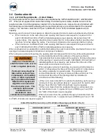
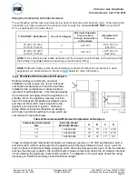
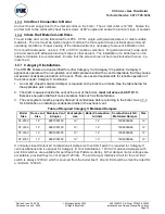
Sizing the Combustion Air Intake Ductwork
The combustion air flow rate requirements per boiler model are summarized in
. When sizing the
combustion air intake ductwork, the pressure drop through this ductwork
MUST NOT
exceed 0.22”
W.C. as described in the table below:
P-K STORM
™
Boiler Model
Flue Vent Category
Maximum Allowable
Pressure Drop
through Combustion
Air Ductwork
Allowable Vent
Pressure
ST-2500, ST-3000,
ST-3500, ST-4000
II
0.22” W.C.
-
0.01” W.C. to
-
0.05” W.C.
ST-2500, ST-3000,
ST-3500, ST-4000
IV
0.22” W.C.
+0.01” W.C. to
+0.22” W.C.
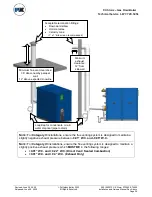
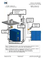
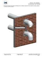
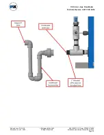
NOTE:
If the combustion air intake ductwork and the exhaust vent terminate on the same wall of
the building, they
must
utilize the same type of termination fitting.
NOTE:
Patterson-Kelley recommends including a motorized combustion air damper in each
appliance’s air intake ductwork. Refer to
more information.
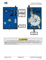
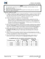
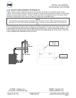
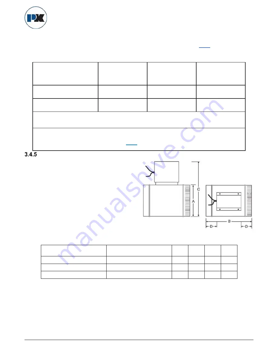
Motorized Combustion Air Dampers
Patterson-Kelley recommends, and most
installation codes require, the use of motorized
combustion air dampers with end limit switches
installed in the combustion air intake ductwork
upstream of each appliance. This damper isolates
the combustion air supply when the appliance is in
standby. Once the appliance receives a call for
heat, the motorized combustion air damper opens,
and the end limit switch must close before the
appliance can proceed to ignition. Patterson-
Kelley offers motorized combustion air dampers
with built-in end limits switches for sale, which are
summarized in the table below:
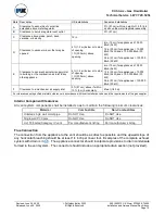
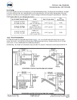
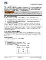
Table of Recommended Motorized Combustion Air Dampers
Combustion Air Ductwork
Size
Normally-Closed
Motorized Damper
A
B
C
D
10
”
10-0490-6945
10
”
10
”
13
”
3.38
”
12”
10-0490-6946
12”
12”
15”
4.38”
14”
10-0490-6989
14”
14”
17”
5.5”
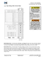
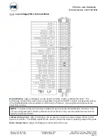
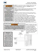
These normally-closed motorized combustion air dampers operate on 120 VAC and feature a built in
end limit switch which must be wired to the appliance
s’ Air Damper Interlock circuit. Upon a call for
heat, the boiler
’s Air Damper Relay energizes, which drives the damper motor open. Once the damper
reaches the fully-open position, the end limit switch makes contact and closes the Air Damper Interlock
circuit, allowing the appliance to proceed to ignition. The diagram on the next page shows the wiring
necessary to install the normally-closed motorized damper.