


7
Secur
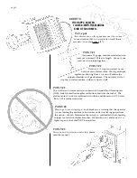
e the rotor in a vice. Service
one hammer assembly at a time. Use
a ball peen hammer and pin punch to
remove the roll pins from each spacer
and shaft as shown.
(Discard the
roll pins. Use new pins during
reassembly.)
Pull out the shaft,
catching the spacers and hammers
with your free hand. Inspect the
shafts and spacers for unusual wear.
Replace them, if necessary.
Reverse each worn hammer,
or replace them as need be. Note
how the Y-hammers are positioned in
relation to one another. Shafts with
two hammers must be reassembled
so that the bent prongs face inward;
the single hammers face their prongs
in opposite, outward directions.
Secure the spacers with new roll pins
using your ball peen hammer and
punch pin.
If not servicing the knives, r
eassemble
your unit by following 1 through 6 in
reverse order.
8
W
ith the chipper cone and base
removed, slowly turn the rotor clock-
wise with a probe until the chipper
knife appears in the hole. Scrape out
any pulp embedded in the heads of
the screws. Loosen the screws using
the 3/16” Allen wrench provided
with your unit. Unscrew them by
hand and remove the knife.
Sharpen the knife evenly at a 30°
angle. A homeowner’s bench grinder
with a fine grit stone will do. But
because the knife is specially heat-
treated, too much heat will make
brittle. So, grind only a little bit at a
time and allow them to cool.
Slow-speed, water-cooled grind-
ing is preferred. For best results, see
your local machine shop specialist.
The knife must be replaced once
the base of its cutting edge is ground
within 1/4” of the mounting holes.
Reassemble your chipper-shr
edder-vac by
following these instructions in reverse.
Sharpen the
chipping knife
when it loses
its self-feeding
action.
Minimum
distance = 1/4”
One hammer,
fork facing outwards.
One hammer,
fork facing in.
CORRECT
“STAGGERING”
OF HAMMERS
SHOWN HERE:
Removing the
knife without
disassembling
the housings.
page 15


