®
Set Up the Hardware
PS
-
3211
3
013-14971A
LED Information
The Bluetooth and the Battery Status LEDs operate as
follows depending on the type of connection:
For a wireless Bluetooth connection:
For a micro USB cable connection to a USB
port
:
For a micro USB cable connection to a USB
charger
:
*Logging: PASCO wireless sensors can either stream
live data to a compatible device for “real-time” viewing or
log data (save it to the sensor’s memory). After logging,
the data can be uploaded to the computing device for
display and analysis at a later time. Logging capability
supports long-term or remote data collection while not
connected to a device.
Check the PASCO Web page at:
www.pasco.com/software
for the latest software version.
Set Up the Hardware
Connecting the Shrouded Test Leads to the
Sensor
•
Connect the boot-shaped shrouded end of the red
test lead to the red voltage jack on the front end of
the sensor.
•
Connect the end of the black test lead to the black
voltage jack on the sensor.
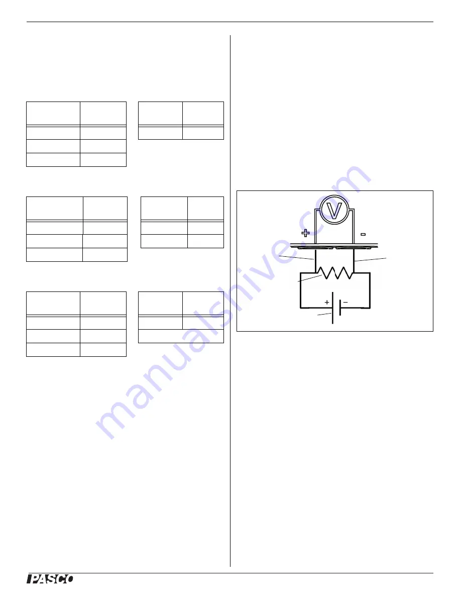
Connecting the Sensor for Measurement
Voltage is measured from one point to another point. For
example, voltage is measured “across” a component in a
circuit. The sensor is connected in parallel to the circuit;
not in series as a part of the circuit.
For example, in the diagram, the alligator clip of the red
test lead is connected to one end of a resistor that is in a
circuit with a battery. The alligator clip of the black test
lead is connected to the other end of the resistor. The
Wireless Voltage Sensor measures the “voltage drop”
across the resistor.
Set Up the Software
SPARKvue
Connecting the Wireless Sensor to a Tablet or a
Computer via Bluetooth
•
For SPARKvue, select the Bluetooth icon to open
the Wireless Devices list. In the Wireless Devices
list, the sensors are ordered by proximity to the
device.
•
Select the correct address that matches the
XXX-XXX number found on the sensor.
Bluetooth
LED
Status
Battery
LED
Status
Red blink
Ready to pair
Red blink
Low power
Green blink
Connected
Yellow blink
Logging*
Bluetooth LED Status
Battery
LED
Status
OFF
--
Yellow ON
Charging
OFF
--
Green ON
Charged
Yellow blink
Logging*
Bluetooth
LED
Status
Battery
LED
Status
Red blink
Ready to pair
Yellow ON
Charging
Green blink
Connected
Green ON
Charged
Yellow blink
Logging*
15 V MAX
15 V MAX
Red Test
Lead
Black Test
Lead
Resistor Symbol
Battery Symbol


