background image

®

Technical Support

 PS

-

3202

11

013-14710C

15. Click Finish. 

Theory of Calibration

One of the functions of the PASCO Data Collection 

Software is to take the stream of raw data from a sensor 

and transform it into the calibrated data that you see in 

the Graph, Table, and other displays. If you do not 

calibrate a sensor yourself, the software uses a default 

calibration that is loaded when the sensor is connected.

You can think of the software as taking in raw data and 

outputting calibrated data. When you perform a 

calibration, the software redefines the linear equation 

that transforms the raw input data into the calibrated 

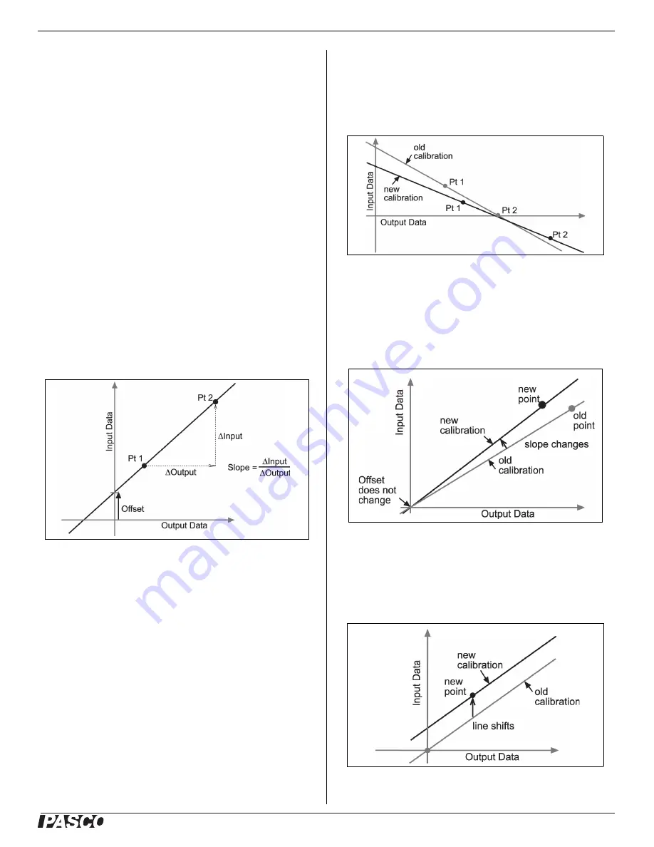
output data. The linear function is of the form:

Raw Input = Slope x Calibrated  Offset

Or:

Calibrated Output = (Raw Input - Offset)/Slope

The function can be represented graphically as a line.

Two points, Pt 1 and Pt 2, define the line. In the 

two-point calibration procedure, each point is reset by 

associating a known standard value (for instance, the 

temperature of ice water) with a raw input measurement 

that the sensor sends out when it is in that standard. In a 

one-point calibration, only one of the points is reset by 

the user.

Types of Calibration

There are three types of calibration: two-point, one-point 

slope, and one-point offset. Any of these calibrations can 

be performed on a single sensor, or simultaneously on 

multiple similar sensors; however, for any given sensor, 

the software will automatically select the most typical 

calibration type as the default setting.

Two-Point

In a two-point calibration, you reset two points to define 

a new line. This type of calibration affects both the slope 

and the offset. 

One-Point Slope

In a one-point slope calibration, you reset only one point. 

The slope of the line changes so that the line intersects 

the new point, while the offset (or Y-intercept) does not 

change. 

One-Point Offset

In a one-point offset calibration, you reset only one point. 

The line shifts so that it intersects the new point, but its 

slope does not change.

Summary of Contents for PS-3202

Page 1: ...res acceleration in three dimensions X Y and Z The PASCO Data Collection Software can show the resultant acceleration The sensor uses a micro electromechanical system MEMS device The sensor is designe...

Page 2: ...shine green when the battery is charged The battery is partially charged at the factory Initial charging time may be three hours or longer depending on the power source and the condition of the batter...

Page 3: ...o when the force or acceleration is actually zero This is a normal behavior that is corrected when you zero or tare the sensor using the PASCO Data Collection Software In SPARKvue the process for sett...

Page 4: ...SB Cable into the micro USB port on the end of the sensor Connect the other end of the Micro USB Cable to a USB port on the computer or into a powered USB hub connected to the computer Zero Tare the F...

Page 5: ...ating with the computer software or tablet application try restarting the software or application If the problem remains press and hold the ON button for 10 seconds and then release Start the sensor i...

Page 6: ...is 1 0 g If the sensor is placed label side down so that the back is facing upward the Acceleration Z axis reading is 1 0 g Mounting the Sensor Mounting the Sensor on a Rod Slide the sensor onto a rod...

Page 7: ...eeks or more because full day continuous sampling would be unusual Even in the most extreme case with a high sample rate the Force Acceleration Sensor battery would support a full day of use before ne...

Page 8: ...ference and 2 this device must accept any interference received including interference that may cause undesired operation CE Statement This device has been tested and found to comply with the essentia...

Page 9: ...hing lower than 0x6 means an older version of Bluetooth Your device will need the PS 3500 USB Bluetooth 4 0 Adapter 1The Mac Mini and MacBook Air were updated with Bluetooth SMART support in 2011 The...

Page 10: ...int 1 click the Standard Value box and enter the known force value that is 9 8 9 Under Calibration Point 1 click Read From Sensor The value measured by the sensor is transferred to the Sensor Value bo...

Page 11: ...each point is reset by associating a known standard value for instance the temperature of ice water with a raw input measurement that the sensor sends out when it is in that standard In a one point ca...

Page 12: ...used to make one sensor agree with another sensor Due to normal variation among probes a second probe might read consistently higher than the first probe Normally this difference would be insignifica...

Reviews: