®
DC Programmable Power Supply
PI-9880
I n s t r u c t i o n M a n u a l
0 12 - 1 2 6 9 5A
*012-12595*
Page 1: ... DC Programmable Power Supply PI 9880 Instruction Manual 012 12695A 012 12595 ...
Page 2: ... DC Programmable Power Supply 012 12695A 2 ...
Page 3: ... Model No PI 9880 012 12695A 3 ...
Page 4: ... Power Supply Table of Contents Contents Introduction 3 Typical Uses 4 Specifications 4 Tutorial 7 Basic Operation 19 Standard Functions Rectangle Ramp and Stair 22 Custom Program 28 Technical Support 35 ...
Page 5: ... 0 18 volts V at up to 1 ampere A You can use the Power Supply as a simple constant voltage source or take advantage of its advanced features to output periodic functions and custom programs Included Equipment Part Number DC Programmable Power Supply PI 9880 AC Power Adapter 100 240 VAC 24 VDC 540 102 ...
Page 6: ... 8947 or Rotational Acceleration Tank ME 8957 TD 8513 Heat Conduction Apparatus Power the apparatus with a positive offset rectangle wave see page 22 or sine wave the Power Supply s default custom program see page 28 General Specifications Output Voltage Adjustment 0 18 V Voltage Adjust Resolution 10 mV Voltage Adjust Accuracy 0 25 of setting or 20 mV whichever is larger Current limit Shutdown Pro...
Page 7: ... direction ascending or descending Alternating stair direction option Programmable number of cycles 1 to 999 or infinite Monitor voltage or current Function 5 SET MAX see page 20 Programmable voltage limit 0 01 18 00 V Programmable maximum current 0 010 1 050 A Automatic shutdown timer 0 01 99 99 hours Hidden Global Maximum voltage 0 01 18 00 V remembered after power off Function 6 PROGRAM Custom ...
Page 8: ...vice is a programmable power source not a function generator The max imum frequency of the rectangle and ramp functions is 10 Hz The maximum fre quency of the default sine wave custom program is about 0 1 Hz The Power Supply is designed for current flow in one direction out of the posi tive terminal and into the negative terminal In the example illustrated below the Power Supply is switched from 0...
Page 9: ...an look at the current draw You can use any resistor from about 20 Ω to 100 Ω but check the power rating to make sure it will not overheat during the tutorial you will apply voltages up to 10 volts Set up POWER and OUTPUT connections 1 Plug the AC adapter into a wall outlet and into the port labeled POWER on the Power Supply 2 Use a pair of banana plug patch cords to connect a load resistor or oth...
Page 10: ...he knob more quickly it changes by 0 04 V per detent Adjust the voltage back to 4 00 V Temporarily switch off output 3 Quickly press and release to temporarily switch off the output The Voltage LED blinks rapidly and the actual output voltage drops to zero though the display still shows the voltage setting Turn the Coarse knob Note that you can adjust the voltage setting while the actual output re...
Page 11: ... display toggling press again to resume Reset output and display 6 Press and hold until the display shows 0 00 Release the button You have just reset the output voltage to zero and the display to voltage For more information about constant DC output see page 19 Function 5 SET MAX Set maximum voltage 1 Turn the Function knob to SET MAX The display briefly shows F5 for Function 5 followed by 18 00 w...
Page 12: ...started yet Display shows auto off Press to start the countdown The Time LED is now lit steadily Turn the Function knob back to Constant DC and set the voltage to 1 V Wait for the remainder of the 36 seconds When the countdown time has elapsed the display shows OFF to indicate that the output has been switched off Press to return the Power Supply to normal operation Setting Hidden Global Maximum v...
Page 13: ... START label printed above the button which indicates what happens when you press the button 4 Try turning the Coarse and Fine knobs the knobs have no effect when the function is running 5 Press and hold for about 1 second to stop running the function Note the STOP label printed below the but ton which indicates what happens when you press and hold the button Minimum voltage set to 2 V 6 Press and...
Page 14: ...50 for a duty cycle of 50 while holding the but ton turn the Coarse knob to change the duty cycle to 10 Press START The output voltage now spends 10 of the time at the maximum voltage and 90 of the time at the minimum voltage Press and hold STOP For more information about the Rectangle Wave func tion see page 22 Function 3 Ramp Ramp with 2 V minimum and 8 V maximum 1 Turn the function knob to Ramp...
Page 15: ...me LED starts blinking fast and the display shows 0 the auto repeat setting while holding the button turn the Fine knob to change the auto repeat setting to 2 Press START to run the function The output now completes two ramps and stops automatically A negative auto repeat setting causes a triangle wave 8 Press DISPLAY so that the Time LED is lit Press and hold SET and adjust the auto repeat settin...
Page 16: ...me to 1 00 s 5 Press START to run the function and observe the waveform Note that the top of the stair is determined by the Power Supply s voltage limit setting Press and hold STOP Stair with a negative auto repeat setting 6 Press DISPLAY so that the Time LED is lit again Press and hold SET the Time LED starts blinking and the display shows the auto repeat setting while holding the button adjust t...
Page 17: ...oltage sensor be sure to stop the program before it exceeds 10 V Scale Factor of 50 3 Turn the Coarse knob to change the Scale Factor to 50 Press START to play the program again each voltage point is now half of what it was before Press and hold STOP Graph type set to 0 4 Press and hold SET the display shows 1 the graph type setting while holding the button turn the Coarse knob to change the graph...
Page 18: ...ative zero Press START to play the program again The program now alternates between playing forward and backward resulting in a positive offset sine wave Press and hold STOP Program stops before exceeding the voltage limit 7 Turn the Function knob to SET MAX and set the voltage limit to 5 V Turn the Function knob back to PLAY Press START to play the program The output will not exceed the voltage l...
Page 19: ...tore that value 4 Press and hold STOP to exit edit mode The display shows P 51 to indicate the num ber of stored points Erase the stored program 5 Press and hold both buttons simultaneously until the display shows EEEE for Erased release the buttons You have just erased the stored program The display now shows P 0 because there are zero stored points 6 To enter a new program press The dis play sta...
Page 20: ... DC Programmable Power Supply 20 T u t o r i a l ...
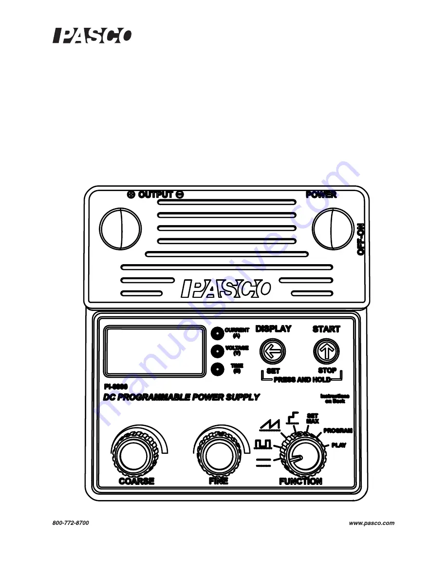
Page 21: ...he digital display Rotate the Coarse knob to adjust the quantity in large steps rotate the Fine knob to adjust it in small steps The Fine knob is speed sensitive rotating it quickly causes a larger change per detent than rotating it slowly The push buttons and are used to select what is shown on the digital display and to control the output In this manual you may be instructed to press a button wh...
Page 22: ...e the output is switched off you can turn the Coarse and Fine knobs to adjust the voltage setting Press again to switch the output voltage back on Over current If output current exceeds the maximum current setting see Maxi mum Values below the output voltage drops to zero the display reads OL for over load and Current LED flashes amber Press START to resume normal operation Reset Output and Displa...
Page 23: ...ed the output voltage drops to zero and the display reads OFF To resume normal operation press either button After setting the time you must press START to start the countdown The maximum setting is 99 99 hours about 4 days You can use this feature to automatically stop an unattended demon stration or display Global Maximum The Global Maximum is a hidden feature that the instructor can use to secu...
Page 24: ...time and low half the time Rectangle Wave Set up 1 Turn the Function knob to The dis play shows the Maximum Voltage parameter and the Voltage LED blinks slowly to show that the Power Supply is in set up mode with no output Turn the Coarse and Fine knobs to set the Maximum Voltage 2 To set the Minimum Voltage press and hold SET until the Voltage LED starts blinking fast While holding the button tur...
Page 25: ...aveforms are illustrated below Ramp Set up 1 Turn the Function knob to The display shows the Maximum Voltage parameter and the Voltage LED blinks slowly to indicate that the Power Supply is in set up mode with no output Turn the Coarse and Fine knobs to set the Max imum Voltage 2 To set the Minimum Voltage press and hold SET until the Voltage LED starts blinking fast While holding the button turn ...
Page 26: ...od depends on its value as summarized below 4 To set the Auto repeat parameter press and hold SET until the Time LED starts blinking fast While holding the button turn the Coarse and Fine knobs to adjust Auto repeat between 999 and 999 To run the Ramp function press START See Standard Functions Run Mode on page 29 for further instructions Period seconds Adjustment increment seconds 999 to 100 1 99...
Page 27: ...unction is always equal to the Power Supply s voltage limit setting Turn the Function knob to SET MAX then turn the Coarse and Fine knobs to adjust the voltage limit 2 Turn the Function knob to The display shows the Step Voltage parameter The Voltage LED blinks slowly to show that the Power Supply is in set up mode with no output Turn the Coarse and Fine knobs to set the Step Voltage Step Time Min...
Page 28: ...the Time LED starts blinking fast While holding the button turn the Coarse and Fine knobs to adjust Auto repeat between 999 and 999 To run the Stair function press START See Standard Functions Run Mode on page 29 for further instructions Special Application Heat Pulse For calorimeters and other apparatus that use heating resistors you may want to drive the resistor with a pulse of a specific volta...
Page 29: ... The Voltage LED light blinks fast and output voltage goes to zero though the paused voltage which may not be zero is shown on the display To continue running the function press again 3 To stop running the function and return the Power Supply to set up mode press and hold STOP you can do this while the function is either running or paused The output stops automatically after the number of repetiti...
Page 30: ...se the buttons The Power Supply returns to Program Home mode with the display showing P 0 to indicate that zero points are stored Follow the Append instructions below to enter a new program Append Use Program Append mode to add points to the end of the existing program or start a new program if zero points are stored 1 From Program Home mode press START to enter Program Append mode The display bri...
Page 31: ...rt another point turn the Coarse or Fine knob to display the index number of the point that you wish to insert in front of and repeat this step 4 When you are finished editing the program press and hold STOP to return to Program Home mode Tips for Designing a Custom Program Before you start entering a program write it on paper or generate it on a com puter in two columns with index numbers in the ...
Page 32: ...he program plays in the only one direction or alternating directions Some examples of parameter combinations and their resulting waveforms are illus trated below For a periodic or repeating function the period depends on the number of programed points the Step Time and the sign of Auto Repeat If Auto Repeat is negative you only need to program the first half of the waveform because the program rep...
Page 33: ...teps times Step Time 4 To set the Auto repeat parameter press and hold SET until the Time LED starts blinking fast While still holding the button turn the Coarse and Fine knobs to adjust Auto repeat between 999 and 999 Play Custom Program 1 To play the custom program turn the Function knob to PLAY and press START The Voltage LED lights steadily to indicate that the display shows the actual output ...
Page 34: ...o and the Voltage LED flashes amber Press and hold to return the Power Supply to set up mode Example Custom Programs The following tables show some examples of programs and settings with the resulting output Time Delay Long Ramp Settings Graph Type Step Time Auto repeat 1 60 s 1 Voltage values 0 0 0 0 5 5 Use a program like this to make the Power Supply wait for a certain interval after you press ...
Page 35: ...ndard step function requires each step to have the same width This custom program allows each step to have a different width Settings Graph Type Step Time Auto repeat 1 0 5 s 0 Voltage values 5 0 0 0 0 0 0 0 0 0 5 5 5 5 5 5 5 0 0 0 The standard square wave function allows you to change the duty cycle but all the pulses must have the same width With this custom program you can create almost any pat...
Page 36: ...programed points follow the function V 0 06 e0 6 t 1 Just 20 points are sufficient for a close approximation of the function Change the Step Time to a negative value for a decreasing exponential Use this program with negative Step Time to simulate a discharging capacitor Settings Graph Type Step Time Auto repeat 0 0 10 s 0 Voltage values 0 3 8 6 32 8 05 9 50 10 75 11 83 12 79 13 64 14 39 15 06 15 ...
Page 37: ...nstruction Manual is copyrighted with all rights reserved Per mission is granted to non profit educational institutions for reproduction of any part of this manual providing the reproductions are used only in their laboratories and classrooms and are not sold for profit Reproduction under any other circumstances without the written consent of PASCO scientific is prohibited Trademarks PASCO PASCO s...
Page 38: ......