background image

Model  No.ME-8236

 Appendix A: Calibration

15

012-13762D

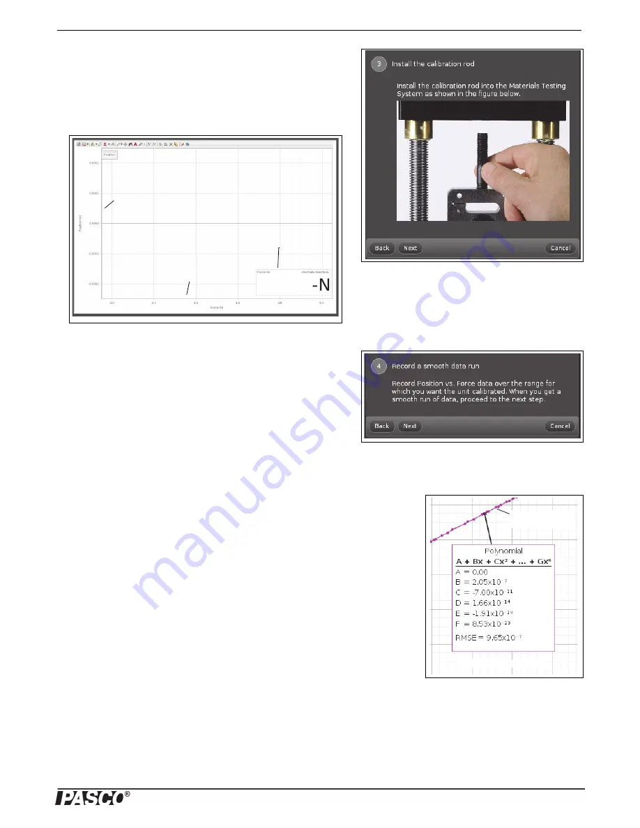
Step Three: Install the Calibration Rod 

The ‘calibration wizard” changes to show an illustration about how to 
install the calibration rod.

In addition to the illustration, a Graph display of Position (m) versus 
Force (N) opens. A Digits display of Force (N) is part of the Graph dis-
play.

Click 

Next

 to show Step Four: “Record a smooth data run”.

Step Four: Record a Smooth Data Run

NOTE: To make a calibration that will accurately correct for compli-
ance, it is necessary to calibrate the Materials Testing Machine over the 
same range of force and the same conditions you expect to use when 
you are testing your samples.

Click 

Record

 and collect a smooth run of position versus force 

data. 

When the data collection is finished, click 

Stop

.

REMINDER: If the run of data is not smooth, delete the run and try again.

NOTE: A Polynomial curve fit is automatically applied to the run of position versus 
force data.

Click 

Next

 to open Step Five, “Polynomial Fit”. 

Position (m)

Force (N)

Digits display of 

Force (N)

Position versus 

force data

Polynomial curve fit

Summary of Contents for ME-8236

Page 1: ...crosshead Tensile Samples 60 Sensor Cable Load Bar Round Nut Velcro Loop Material Safety Shield 2 Velcro Hook Material WARNING Provide proper eye protection when using the Materials Testing Machine or its Accessories Operate the Materials Testing Machine behind protective Safety Shields Crankshaft Base USB Link Items from the ME 8230 Materials Testing System Materials Testing Machine ...

Page 2: ...ed and analyzed by a PASCO Interface with PASCO Data Collection Software The sensor cable from the Materials Testing Machine con nects to a PASPORT input port See the PASCO catalog or web site at www pasco com for more information about PASCO interfaces and data collection software Included Items Included Items Materials Testing Machine Calibration Rod and Nut Load Bar Round Nut Safety Shield 2 Re...

Page 3: ...rdered separately The table shows typical values Accessories Table 2 lists accessories and adapters that are included in the Comprehensive Materials Testing System and are available separately for the Material Testing Machine Other accessories and adapters are being developed Replacement Items Also available separately are replacement items such as the previously mentioned Tensile Samples the Mate...

Page 4: ...tware includes a cali bration wizard that allows the calibration information called a compliance calibration for the Materials Testing Machine to be stored for later use PASCO Capstone is pro vided in the ME 8230 Materials Testing System Lab 02 Compliance Calibration Tutorial NOTE A PASCO Capstone workbook file about compliance calibration is available to download from the PASCO web site Go to www...

Page 5: ...the Calibration Rod for Compression To mount the calibration rod for compression screw the short threaded end of the rod into the top of the load cell Screw the calibration nut onto the top threaded part of the calibration rod until the nut is at the bottom of the threaded section Lower the load bar until the bottom of the load bar rests on the top of the calibration nut Attach the Safety Shields ...

Page 6: ...upport anvils and a small hex key allen wrench The plunger is mounted on the bottom of the load bar using the sample nut The base for the adjustable anvils is screwed onto the top of the load cell The spacing between the two triangular support anvils can be adjusted Use the hex key to loosen the screws holding the anvils and slide them closer together or farther apart Tighten the screws securely U...

Page 7: ...r and adjust the position of the shields if needed Materials Shear Accessory ME 8239 The Materials Shear Accessory consists of two pieces of hardened steel a front piece and a back piece held together by a pair of permanent screws and a package of Materials Shear Samples The front piece can slide vertically relative to the back piece which is designed to be mounted on the load cell using an includ...

Page 8: ...ss with the sec ond polarizer on the other side of the load bar Place a light source so that it shines through the polarizers from behind Materials Structure Beam Adapter ME 8242 The PASCO Structures System includes a variety of beams that can be used with the Materials Testing Machine The beams are models of I beams and other structure elements The Materials Structure Beam Adapter is designed to ...

Page 9: ...ng that hold materials in place and have a threaded 10 32 hole designed for mounting the device on a materials tester such as the Materials Testing System The Materials 10 32 Adapter is designed to connect devices with a threaded 10 32 hole to the Load Bar and Load Cell of the Materials Testing Machine The 10 32 Adapter with the longer larger diameter threaded section is mounted in the Load Bar of...

Page 10: ... the two sizes of I beams The 3 I Beam is 11 5 cm long and the 4 I Beam is 17 cm long Thin I Beams ME 7012 The Thin I Beams set consists of 48 thin I Beams of two sizes 3 Beam 24 and 4 Beam 24 The beams are like those in the PASCO Structures Systems but there are no holes in the web area Therefore when used with the Materi als Testing Machine the test results are more like the results would be for...

Page 11: ...ng the reproductions are used only in their laborato ries and classrooms and are not sold for profit Reproduction under any other circumstances without the written consent of PASCO sci entific is prohibited Trademarks PASCO PASCO Capstone PASPORT SPARK Science Learning System SPARK SLS and SPARKvue are trademarks or registered trademarks of PASCO sci entific in the United States and or in other co...

Page 12: ...pplied Although it is possible to use the Materials Testing Machine with negative values for force and position it is easier to change the sign convention to be positive while you use the Calibra tion Wizard for the calibration procedure To change the sign for the force and position data click the Hard ware Setup icon in the Tools palette In the Hardware Setup window click the Properties icon shap...

Page 13: ...you to create select save modify and delete calibrations Create New Calibration This is the default choice In this selec tion the calibration wizard will take you through the steps needed to create and save a new compliance calibration This includes prompting you to install the calibration rod Step Three record a data run on the graph provided Step Four and create a polynomial curve fit Step Five ...

Page 14: ...nish to delete the calibration If you select Rename Calibration the default choice and click Next a text window opens and you can enter a new name for a calibration ADVICE Create a name that includes the maximum force used It is also helpful to record any pre load that is used Click Finish after entering a name If you select Save Calibration in Sensor and click Next the win dow shows Store Calibra...

Page 15: ...alibration that will accurately correct for compli ance it is necessary to calibrate the Materials Testing Machine over the same range of force and the same conditions you expect to use when you are testing your samples Click Record and collect a smooth run of position versus force data When the data collection is finished click Stop REMINDER If the run of data is not smooth delete the run and try...

Page 16: ... determine if the new coefficients made a better curve fit Step Six Name the Calibration Type a name for the calibration in the text area Example names might be Calibration 7000 or Tension Calibration Click Finish to store the calibration as part of the Capstone file Finishing Step NOTE The Calibration window goes back to Step One When you click Next the Choose Calibration Action window Step Two w...

Page 17: ...Model No ME 8236 Appendix A Calibration 17 012 13762D From the File menu save the Capstone file for future use ...

Page 18: ...display 5 With data still being recorded slowly turn the crank back counter clockwise Watch the Digits display and turn the crank to reduce the force to between 10 and 20 N Don t let the force go back to zero 6 Turn the crank clockwise to increase the force as before Notice how the second plot of data looks on the graph compared to the first If the second plot of data tracks on top of the first pl...

Reviews: