Instruction Manual
012-07227G
*012-07227*
Basic Electrostatics System
ES-9080A
Page 1: ...Instruction Manual 012 07227G 012 07227 Basic Electrostatics System ES 9080A ...
Page 2: ... Pail 9 Conductive Spheres 10 Conductive Shapes 10 Electrometer Operation and Setup Requirements 11 Suggested Demonstrations 13 34 Demonstration 1 Faraday Ice Pail and Charge Production 13 16 Demonstration 2 Charge Distribution 17 20 Demonstration 3 Capacitance and Dielectrics 21 30 Demonstration 4 Charging and Discharging Capacitors 31 34 Technical Support Copyright and Warranty Information 35 Pr...
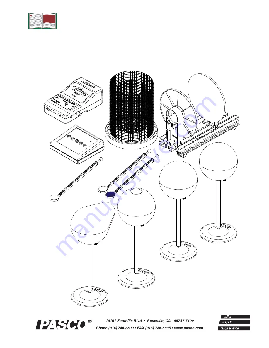
Page 3: ...r 1 Basic Electrometer cables not shown ES 9078A 2 Electrostatics Voltage Source cable and AC adapter not shown ES 9077 3 Basic Variable Capacitor cable not shown ES 9079 4 Faraday Ice Pail and Shield ES 9042A 5 Charge Producers 2 and Proof Plane 1 ES 9075B 6 Conductive Spheres 2 ES 9059B 7 Conductive Shapes 2 ES 9061 1 2 3 4 5 5 6 7 ...
Page 4: ...Electrometer ES 9078 in a computer screen that all can easily see You can use an analog display for example to show the deflections of the needle or a digits display to show the voltage If a computer is not available set the basic electrometer upright to allow the meter to easily be seen Always consider how the equipment arrangement may affect charge distributions For example a misplaced power sup...
Page 5: ...itance of the electrometer must be considered when calculating the magnitude of a charge from the voltage reading of the electrometer See Demonstration 3 for the procedure necessary to determine the electrometer s capacitance By following the above principles and by practicing the demonstrator should have a high degree of success with the demonstrations and find their educational effect of great v...
Page 6: ...ly for experiments in electrostatics It has outputs at 30 volts DC for capacitor plate experiments and 1 kV 2 kV and 3 kV outputs for the Faraday ice pail and conductive sphere experiments All of the voltage outputs except for the 30 volt output have a series resistance associated with them which limits the available short circuit output current to about 8 3 microamps The 30 volt output is regulat...
Page 7: ...ically Keep the plate supports clean to prevent charge leakage from the plates Charge Producers and Proof Plane ES 9057B The Charge Producers and the Proof Plane are electrostatic components for use with the PASCO Electrostatic System The charge producers are used to generate charges by contact The proof plane is used to measure charge density on a charged surface The charge producers consist of t...
Page 8: ...ycarbonate about 1014 The proof plane can be used to sample the charge density on charged conductive surfaces A Faraday Ice Pail and Electrometer can then be used to measure the charge density on the proof plane see Figure 6 By touching the proof plane to a surface the proof plane will acquire the same charge distribution as the section of the surface it touched By measuring the charge on the proo...
Page 9: ...m The outer cylinder is called the shield It provides complete visibility to the inside of the pail and when grounded helps eliminate stray charges and AC fields The inner cylinder is the actual pail The pail is mounted on insulated rods the pail is 10 cm in diameter and 15 cm high When a charged object is placed inside the pail but without touching it a charge of the same magnitude is induced on ...
Page 10: ...imize charge leakage from the sphere Conductive Shapes ES 9061 The conductive shapes are special objects upon which to store electrical charges Both shapes are made of nickel plated ABS plastic The Conductive Hollow Sphere is 13 centimeters cm in diameter and has a 3 8 cm 1 5 inch diameter hole at the top that allows access to the inside of the sphere The Conductive Conical Shape is spherical on o...
Page 11: ...r charge the setup procedure should be followed each time you turn on the electrometer Warning To avoid electrical shock and or injury observe the following safety precautions 1 Never use the electrometer for measuring potentials more than 100 volts 2 Never connect the electrometer to an electrostatic generator such as a Van de Graff generator of a Wimshurst machine 3 Never touch the signal input ...
Page 12: ... 2 Shorting the test leads together is insufficient There may still be stray charges within the electrometer circuitry 3 For good results it is essential that the electrometer be connected to an earth ground a water pipe the ground wire from a 120 VAC socket or the COM port on the electrostatics voltage source Only an earth ground provides a sufficient drain for excess charges that may build up du...
Page 13: ...is can tell us the type of charge in the ice pail Equipment Setup Introduction The purpose of this demonstration is to investigate the relation between the charge induced on the ice pail by a charged object placed in the pail and the charge of the object This demonstration is also useful for investigating the nature of charging an object by contact as compared to charging it by induction and to de...
Page 14: ...should read zero when grounded indicating there is no charge in the ice pail Press the ZERO button to completely remove all charge from the electrometer and the ice pail 2 Always start with the voltage range in the higher setting 100 V and adjust down if needed Analog meters are typically most accurate in the range of 1 3 to 2 3 of full scale 3 The charge producers will be used as charged objects ...
Page 15: ... disk ground the ice pail to remove all charge Press the ZERO button to remove residual charges from the electrometer Insert the charge producer again into the ice pail Does any charge remain on it Procedure 1B Conservation of Charge 1 Starting with initially uncharged charge producers rub the blue and white materials together Follow the general procedure for charging listed in part 1A except that...
Page 16: ... Extra Things to Try 1 Try repeating Procedure 1A with the opposite charged wand 2 Try rubbing the white charge producer with a proof plane then measure the magnitude and polarity of the charges produced 3 Try rubbing the blue material with a proof plane Measure the magnitude and polarity of the charges produced 4 Construct a list of materials such that if a material lower in the list is rubbed wi...
Page 17: ...tude or even in sign This occurs for non uniform charge distribution Alternately you may observe that everywhere on the surface the charge has the same magnitude and sign This occurs for uniform charge distribution An important aspect of measuring charge distributions is charge conservation The proof plane removes some charge from the surface it samples If the proof plane is grounded after each me...
Page 18: ...trostatic Voltage Source ES 9077 The voltage source should be grounded to the same earth ground as the shield and the electrometer An earth ground for the system is the AC adapter power supply for the Electrostatic Voltage Source The connected sphere will be used as a charged body 3 Momentarily ground the other sphere to remove any residual charge from it 4 Start the demonstration by sampling and ...
Page 19: ...harge inside the sphere Analysis 1 How do the charges compare between the outside of the hollow sphere and the inside of the hollow sphere Extra Things to Try 1 To show that the charge on a conductor always resides on the outside surface bend a flexible sheet of metal into a cylinder Charge the cylinder and measure the charge density in the inner and outer surfaces Notice that charge is always on ...
Page 20: ...Basic Electrostatics System ES 9080A 20 ...
Page 21: ...s an infinite impedance voltmeter in parallel with a capacitor as shown in Figure 3 1 The capacitor CE represents the internal capacitance of the electrometer plus the capacitance of the leads Whenever you want quantitative measurements of charge voltage or capacitance you need to consider the effect of the internal capacitance of the electrometer unless you are certain that the capacitor you are ...
Page 22: ...ge the capacitor with a known voltage V not higher than 100 V the limit of the electrometer 3 Remove the charged capacitor from the power supply used to charge it being careful not to ground it in any way to avoid removing the charge 4 Connect the charged capacitor across the electrometer input leads Note the voltage VE indicated by the electrometer 5 Calculate the internal capacitance of the elec...
Page 23: ... transfer charge from the charged sphere to the capacitor plates The charge is transferred merely by touching the proof plane to the sphere and then to one capacitor plate If you always touch the sphere and the capacitor plate at the same place equal amounts of charge will be transferred each time Question Why is it sufficient to touch only one plate of the capacitor 4 Observe how the potential di...
Page 24: ...n use it to examine the charge density of the capacitor using the ice pail to measure the charge Investigate the charge density at various points on the plates both on the inner and the outer surfaces How does the charge density vary over the plate 3 Choose a point near the center of one capacitor plate and measure charge density in this area at different plate separations Keep in mind whether you...
Page 25: ...on the voltage source 2 Keep the plate separation constant and change the potential across the plates by changing the setting of the voltage source You have to move the connecting cable from the 3000 V to the 2000 V port Examine the charge density near the center of one capacitor plate How does the charge vary with the voltage Repeat with 1000 VDC Figure 3 3b Demonstration Setup To AC power adapte...
Page 26: ...r reading of about 1 5 scale 3 Increase the plate separation and note the electrometer s readings at various separations How does the potential vary with capacitance NOTE An alternative method is to charge one of the spheres and then transfer some charge to the capacitor The charge however will not be as high Procedure 3C Dielectric Coefficients The dielectric coefficient is the dimensionless fact...
Page 27: ... choose one to keep fixed and the other to be the movable one 1 Connect the electrometer across the plates of the capacitor and set the separation between the plates to about 3 mm 2 Raise the side of the set up nearest the movable plate by setting a block about 3 cm high below it as shown in Figure 3 5 3 Use the voltage source to momentarily touch the plates and charge them to about 4 5 full scale...
Page 28: ...t the dielectric Let qE be the charge on CE the internal capacitance of the electrometer Let Vi be the initial reading of the electrometer The total charge in this initial system is given by qp qE Cp CE Vi After inserting the dielectric Let q p be the new charge on the capacitor plates the capacitance is now C p Let q E be the new charge on CE the internal capacitance of the electrometer Since the...
Page 29: ...on is to examine the effect of placing capacitors in series and in parallel You will need two capacitors of known value between 200 400 µF to ignore the internal capacitance of the electrometer a DC voltage source the electrometer some cables and a double throw switch Material Vacuum 1 Air 1 00059 Polystyrene 2 6 Paper 3 7 Pyrex 4 7 Mica 5 4 Porcelain 6 5 C p Cp CE Vi V f CpVi CpVf Ad OAd C p Cp V...
Page 30: ...values of capacitance determine the amount of charge in each of them Q1 and Q2 7 Questions Can you find a relation between V1 V2 and the voltage of the source How does Q1 and Q2 relate to the original charge on C1 3D 2 Capacitors in Parallel 1 Make sure all capacitors are uncharged before connecting them to the circuit 2 Set up the parallel circuit as shown in Figure 3 7b 3 Set the voltage source ...
Page 31: ...ange so that the internal capacitance of the electrometer needs not be considered You can adjust the resistance value for a convenient RC constant There are two variations of the same activity presented here The first uses a direct DC voltage source and results are obtained in a voltage vs time graph Use higher resistances 10 90 k for this method The second uses a signal generator with a square wa...
Page 32: ...the experiment with different values of R and notice the differences in charging time Analysis When a capacitor is charged through a resistor from a DC power supply the charge on the capacitor and the voltage across the capacitor increase with time The voltage V as a function of time is given by V V0 1 e t RC where V0 is the charging voltage After a time t RC one time constant the voltage across t...
Page 33: ...scharge equals the period of the wave Note The procedure listed here specifies values for R C and the frequency of the signal that work well together If you decide to use any other R or C value you have to adjust the frequency of the wave Notice that the voltage has to remain constant for enough time to fully charge the capacitor before the voltage goes to zero and the capacitor is discharged A go...
Page 34: ...y 0 45 Hz Set the signal generator to AUTO In this way the signal will turn on and off as you press Start or Stop to collect data 4 Start recording data Observe the behavior of the voltage across the capacitor on the screen When several cycles of charging discharging have completed stop the collection of data 5 Only one full cycle is necessary to complete all the analysis Zoom in to a full cycle o...
Page 35: ...product which is deemed to be defective in material or workmanship The warranty does not cover damage to the product caused by abuse or improper use Determination of whether a product failure is the result of a manufacturing defect or improper use by the customer shall be made solely by PASCO scientific Responsibility for the return of equipment for warranty repair belongs to the customer Equipmen...
Page 36: ...l laws and regulations to ensure that it will be recycled in a manner that protects human health and the environment To find out where you can drop off your waste equipment for recycling please contact your local waste recycle disposal service or the place where you purchased the product The European Union WEEE Waste Electronic and Electrical Equipment symbol and on the product or its packaging in...