®
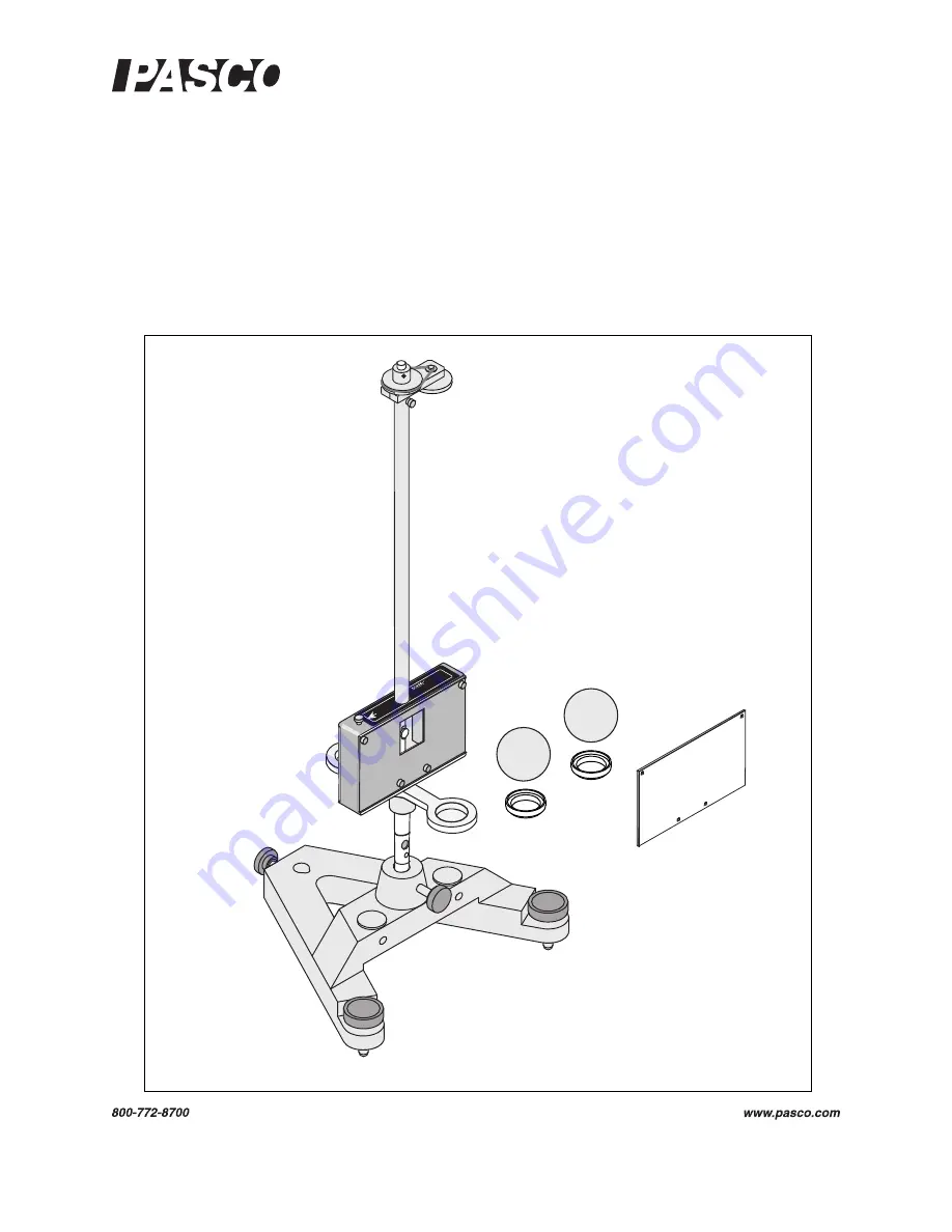
Gravitational Torsion Balance
AP-8215A
I n s t r u c t i o n M a n u a l w i t h
E x p e r i m e n t G u i d e a n d
T e a c h e r s ’ N o t e s
0 12 - 11 0 3 2 C
*012-11032*
Att
a
ch to
E
a
rth
Gro
u
nd.
GR
AV
ITAT
IO
NA
L
TO
RS
IO
N B
ALA
NC
E
AP-
8
215


