!"#$$%"&'()*"+,-./0-1-,
23456
Instruction Manual andExperiment Guide for thePASCO scientificModel AP-8215
6#7869%67:
##;$%
GRAVITATIONAL TORSION BALANCE
Attach to
Ear
th
Ground.
GRA
VIT
ATIONAL
TORSION B
ALANCE
AP-8215
Page 1: ... 1 23456 Instruction Manual and Experiment Guide for the PASCO scientific Model AP 8215 6 7869 67 GRAVITATIONAL TORSION BALANCE A tt a c h to E a rt h G ro u n d GRAVIT ATIO NAL TORSIO N BALANCE AP 8 215 ...
Page 2: ... an equilateral triangle is intended to alert the user of the presence of important operating and maintenance servicing instructions in the literature accompanying the device 0 1 2 3 4 3 04 450 65227 0 0 0 5 4 08 9 2 0 2 3 8 3 4 2 6 4 6 3 4 1 0 22 0 4 2 5 4 08 9 2 0 2 3 ...
Page 3: ...222222222222222222222222222222222222222222222222222222222222222222222222222222222 P 8 1 22222222222222222222222222222222222222222222222222222222222222222222222222222222222222222222222222222222222222222222222 3Q 0 O9 922222222222222222222222222222222222222222222222222222222222222222222222222222222222222222222222222222222222222222222222222 33 6BCDE F 8 3 818 G 673 G 31 J 2222222222222222222222222222...
Page 4: ...1 7 01 9 66 1 6 9 D 6 6 12 GX 7 9 1 FO 76 6 6 0 D 5 67 0 D 0 9 67 0 N 0 F 1 FO N 0 O2I 66 0 9 9 D 0 0 5 67 0 D 6 N F 6 1 FO 8 SM 9 0 D 2 012 34 54 2 J 8 8OY D 1 6 9 7 0 9 FC 6O 9 09 F N2 Equipment Return 1 6 1 F 0 1 8 SM 9 0 D D 0O 9 0W 0 DO 8 SM 9 0 D FO W 6 0 W D K 4YME4 0 0 6 1 2 Z6 0 0 D 0W 0 0 01 9 66 0 09 09 N F 6 76 O 99 12 PDB6F M 4 Z 8 4 _ 4 SS48 4X YME E4 ZE _ VMZ Z VME H M YEM 8 SM2 _ 0...
Page 5: ...rth is obvious The gravitational attraction of every object to every other object however is anything but obvious Despite the lack of direct evidence for any such attraction between everyday objects Isaac Newton was able to deduce his law of universal gravitation However in Newton s time every measurable example of this gravitational force included the Earth as one of the masses It was therefore i...
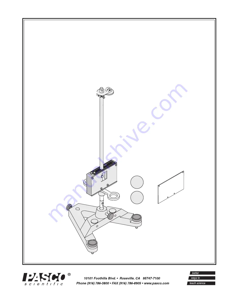
Page 6: ... 004 06788 2 56 x 1 8 Phillips head screws 4 Phillips screwdriver not shown AdditionalRequired laser light source such as the PASCO OS 9171 He Ne Laser meter stick Figure 2 Equipment Included 1 5 kg lead masses replacement torsion ribbon plastic demonstration plate aluminum plate leveling sight large mass swivel support pendulum mirror zero adjust knob torsion ribbon head 2 56x1 8 Phillips head sc...
Page 7: ...best results use a very sturdy table such as an optics table 2 Carefully remove the Gravitational Torsion Balance from the box and secure it in the base 3 Remove the front plate by removing the thumbscrews Figure 3 and carefully remove the packing foam from the pendulum chamber Note Save the packing foam and reinstall it each time the Gravitational Torsion Balance is transported 4 Fasten the clear...
Page 8: ...ng the leveling sight to level the Gravitational Torsion Balance Look through the sight to view the reflection of the pendulum bob in the mirror Pendulum bob must be centered over the mirror pendulum mirror torsion ribbon torsion ribbon head Figure 4 Lowering the locking mechanism to release the pendulum bob arms Turn locking screws clockwise locking mechanisms pendulum bob arm 2 Adjust the feet o...
Page 9: ...from the mirror You will need to point the laser so that it is tilted upward toward the mirror and so the reflected beam projects onto the projection surface Figure 8 There will also be a fainter beam projected off the surface of the glass window Note Vertical adjustment is only necessary at initial setup and when you change the torsion ribbon or if someone has loosened the retaining screw by mist...
Page 10: ... the projection surface the laser beam reflections are not aligned vertically loosen the zero adjust thumbscrew turn the zero adjust knob slightly to refine the rotational alignment of the pendulum bob arms Figure 10 and wait until the movement of the pendulum stops or nearly stops e Repeat steps 4a 4c as necessary until the spots are aligned vertically on the projection surface 5 When the rotatio...
Page 11: ...urs to reach resting equilibrium To shorten the time required dampen the oscillation of the pendulum by smoothly raising the locking mechanisms up by turning the locking screws until they just touch the crossbar holding for several seconds until the oscillations are dampened and then carefully lowering the locking mechanisms slightly Figure 11 Attaching the grounding strap to the grounding screw c...
Page 12: ...mine the gravitational constant G from the motion of the small masses In Method I the final deflection method the motion is allowed to come to resting equilibrium a process that requires several hours and the result is accurate to within approximately 5 In method II the equilibrium method the experiment takes 90 minutes or more and produces an accuracy of approximately 5 when graphical analysis is...
Page 13: ...e only unknowns in equation 1 4 it is necessary to observe the oscillations of the small mass system when the equilibrium is disturbed To disturb the equilibrium from S1 the swivel support is rotated so the large masses are moved to Position II The system will then oscillate until it finally slows down and comes to rest at a new equilibrium position S2 Figure 14 At the new equilibrium position S2 ...
Page 14: ... 9 are known or measurable r 9 55 mm d 50 mm b 46 5 mm m1 1 5 kg L Measure as in step 1 of the setup By measuring the total deflection of the light spot ΔS and the period of oscillation T the value of G can therefore be determined Procedure 1 Once the steps for leveling aligning and setup have been completed with the large masses in Position I allow the pendulum to stop oscillating 2 Turn on the l...
Page 15: ...ass support 4 Immediately after rotating the swivel support observe the light spot and record its position S1 5 Use a stop watch to determine the time required for one period of oscillation T For greater accuracy include several periods and then find the average time required for one period of oscillation Note The accuracy of this period value T is very important since the T is squared in the calc...
Page 16: ...of F Using the equation F Gm1 m2 b2 it can be determined that b b3 b2 4d2 3 2 From Figure 17 Fnet F f F bF F 1 b where Fnet is the value of the force acting on each small sphere from both large masses and F is the force of attraction to the nearest large mass only Similarly G G0 1 b where G is your experimentally determined value for the gravitational constant and G0 is corrected to account for th...
Page 17: ...e position and time for about 45 minutes 3 Rotate the swivel support to Position I Repeat the procedure described in step 2 Note Although it is not imperative that step 3 be performed immediately after step 2 it is a good idea to proceed with it as soon as possible in order to minimize the risk that the system will be disturbed between the two measurements Waiting more than a day to perform step 3...
Page 18: ...g large mass m1 is given by the law of universal gravitation F Gm1 m2 b2 3 1 This force is balanced by a torque from the twisted torsion ribbon so that the system is in equilibrium The angle of twist θ is measured by noting the position of the light spot where the reflected beam strikes the scale This position is carefully noted and then the large masses are moved to Position II The position chang...
Page 19: ...ly equation 3 3 can be used to determine G Given the nature of the motion damped harmonic the initial acceleration is constant to within about 5 in the first one tenth of an oscillation Reasonably good results can therefore be obtained if the acceleration is measured in the first minute after rearranging the large masses and the following relationship is used G b2 a0 2m1 3 4 The acceleration is me...
Page 20: ...Construct a graph of light spot displacement ΔS S S1 versus time squared t2 with t2 on the horizontal axis Figure 20 Draw a best fit line through the observed data points over the first minute of observation 2 Determine the slope of your best fit line 3 Use equations 3 4 and 3 6 to determine the gravitational constant 4 The value calculated in step 3 is subject to a systematic error The small sphe...
Page 21: ...ips screw being sure the copper disc on the tab is in contact with the torsion ribbon head Figure 22 Align the tab with the face of the torsion ribbon head Turn locking screws until locking mechanism anchors the pendulum arms Loosen the Phillips screw locking mechanism broken torsion ribbon Grasp the pendulum bob here to stabilize it Loosen the Phillips screw Figure 21 Securing the pendulum bob be...
Page 22: ...ing straight down the center of the tube If it is not lower the locking mechanisms be sure the torsion wire is centered and raise the locking mechanisms again Repeat as necessary until the ribbon is centered in the tube d Reinstall the packing foam into the chamber to secure the pendulum bob e Replace the plate 2 The Gravitational Torsion Balance may be stored flat in its shipping container 3 Stor...
Page 23: ...web www pasco com Contacting Technical Support Before you call the PASCO Technical Support staff it would be helpful to prepare the following information If your problem is with the PASCO apparatus note Title and model number usually listed on the label Approximate age of apparatus A detailed description of the problem sequence of events in case you can t call PASCO right away you won t lose valua...
Page 24: ......