


English
– 11
SETTINGS AND ADJUSTMENTS
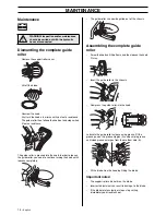
•
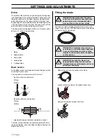
Loosen the knob to offload the springs.
•
Pull out the lock for the front handle and move the handle
to the service position.
•
Remove the three screws holding the support roller guard
using a 6 mm hex key and lift off the cover.
•
Fit the blade.
CAUTION! The blade has two grooves (A) on one side that
act as guide grooves for the guide rollers.
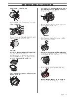
Ensure that the V-shaped edge of the blade enters the
drive wheel and that the blade’s guide groove fits in the
guide rollers. Also see under the heading Drive.
•
Press in the guide roller if necessary, so that it climbs into
the groove on the blade.
•
Fit the support roller guard and ensure that the flanges on
the guide rollers still enter the blade’s grooves correctly.
Now tighten the three screws fully.
•
Rotate the blade and make sure that the support rollers
are not clamped against the blade.
•
Adjust the adjuster screws so that the support rollers
make contact against the blade.
•
Adjust so you can easily stop the support rollers using
your thumb when the blade is rotated. The support rollers
should only follow the blade occasionally.
•
Tighten the locking nuts on the support roller guard.
•
Rotate the blade and make sure you can still hold the
rollers with your thumb when the blade is rotated.
Summary of Contents for K3600 MKII
Page 21: ......
Page 22: ... z x 6r z x 6r ...
Page 23: ......
Page 24: ... z x 6r 2004 12 22 z x 6r 1088929 26 www partner industrial com ...


