C H A P T E R 5 R E P L A C I N G F I E L D R E P L A C E A B L E U N I T S ( F R U s )
64
65
C H A P T E R 5 R E P L A C I N G F I E L D R E P L A C E A B L E U N I T S ( F R U s )
64
65
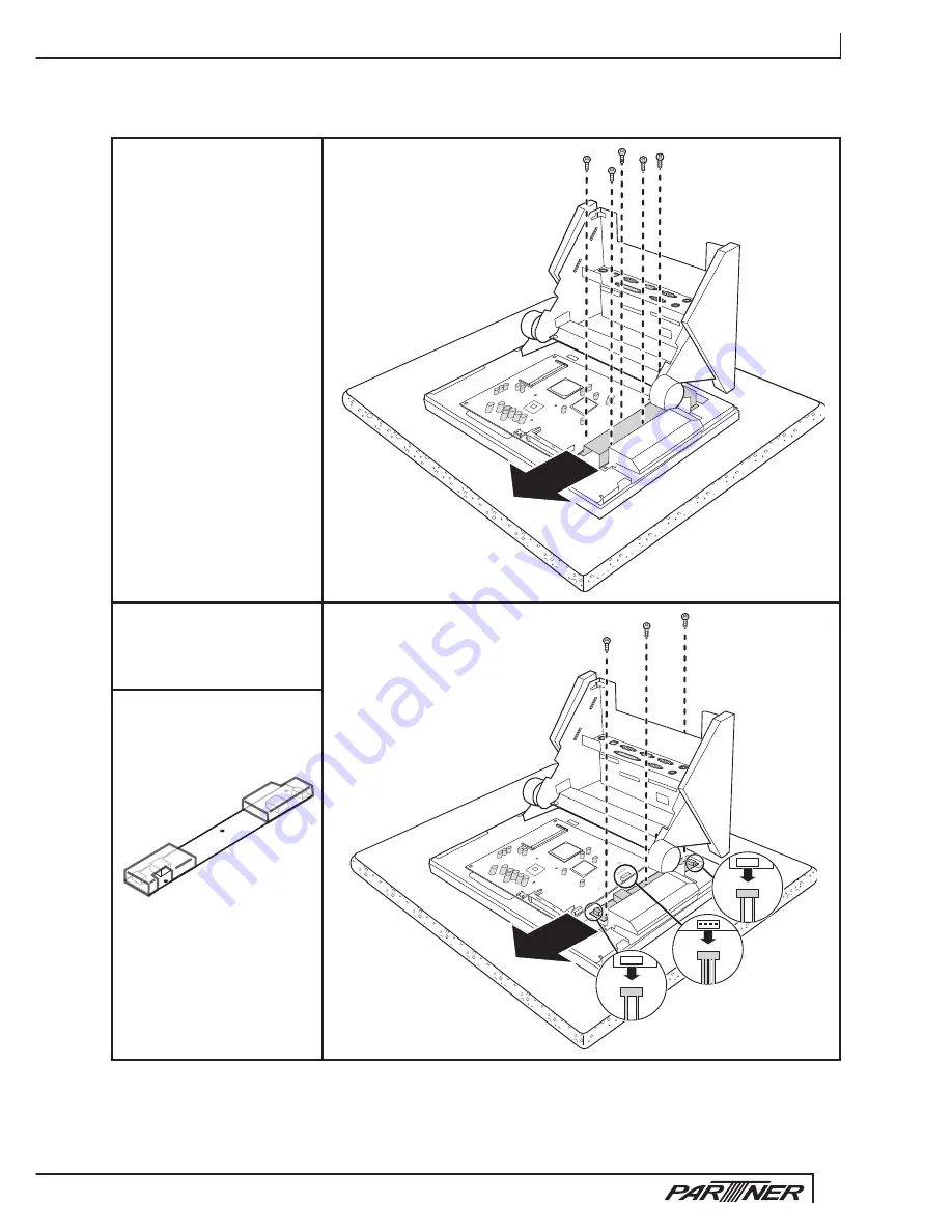
Inverter
Before proceeding, remove
the following FRUs.
“Rear base cover” on
•
page 55.
“Front base cover” on
•
page 56.
“Customer display” on
•
page 58 or 59.
“Back top cover and
•
bottom cover” on page
60 or 61.
Remove the 5 screws (M3
1.
x 4 mm, silver).
Remove the EMI cover.
2.
Remove the 3 screws (M3
3.
x 4 mm, silver).
Disconnect the 3 cables.
4.
Remove the inverter.
5.
When replacing:
Put the inverter in the plastic
cover before replacing it.
Summary of Contents for PT-6910 series
Page 1: ...PT 6910 Series Service Manual...
Page 2: ......
Page 8: ...vi...
Page 43: ...35 Click 5 Next to continue Click 6 Next to continue...
Page 49: ...41 Click 6 Next to continue Click 7 Next to continue...
Page 52: ...C H A P T E R 3 I N S TA L L I N G D R I V E R S A N D S O F T W A R E 44...
Page 78: ...C H A P T E R 5 R E P L A C I N G F I E L D R E P L A C E A B L E U N I T S F R U s 70...
Page 81: ...73 73 Exploded diagram of PT 6915 Figure 6 2...
Page 86: ...A P P E N D I X 78...


