background image

St. Bernard Installation Instructions 

  Page 3 of 19 


Battery and Router Installation 

Step 1: Mount the ChargeTech 54K battery pack to the cover plate (St. Bernard G only). 

A.


This step only applies to the St. Bernard G. 

B.


Remove the cover plate from the enclosure. 

C.


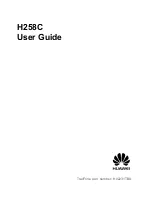
Remove the pads from the side of the battery pack, shown in Figure 1. 

D.


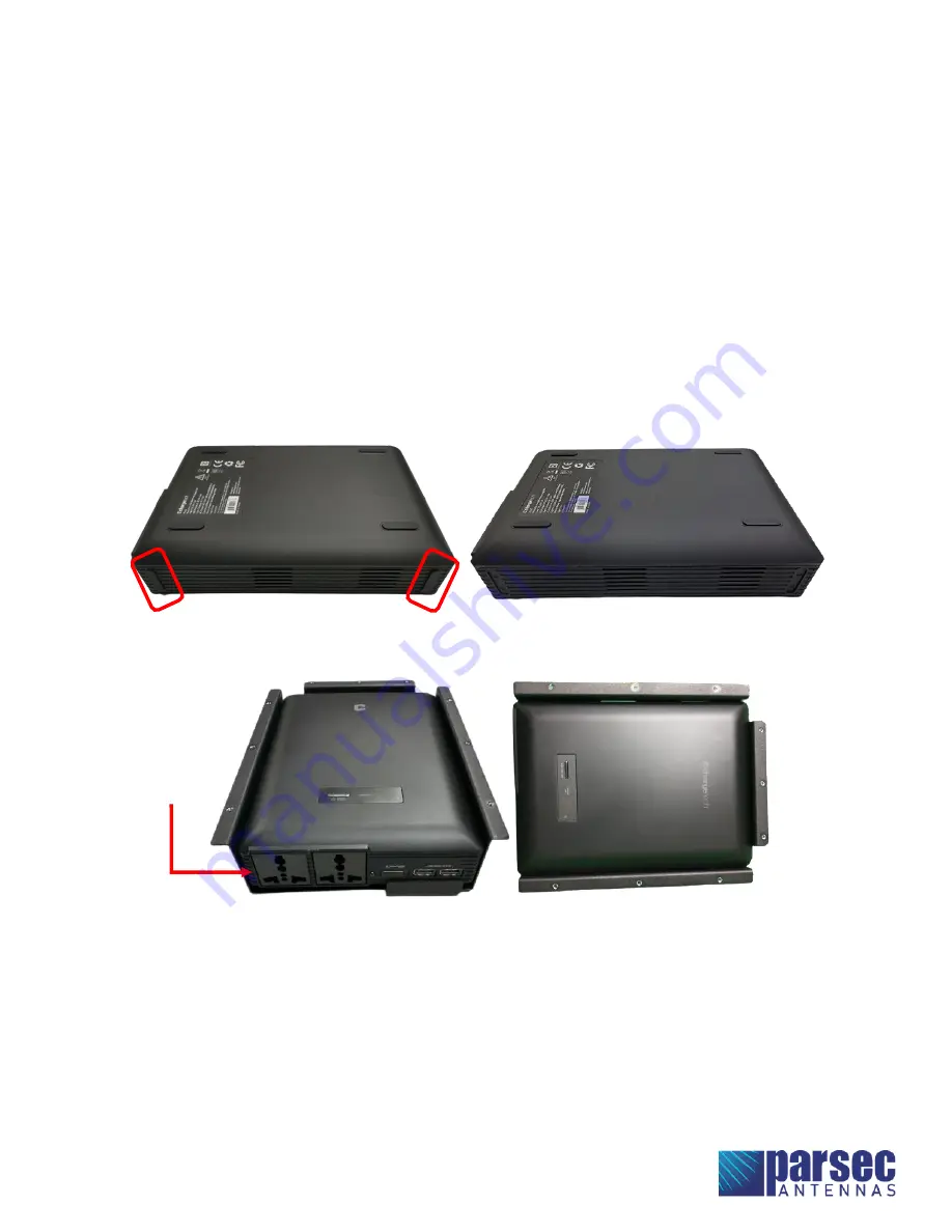
Insert the battery pack into the battery tray, as shown in Figure 2. 

Ensure that the battery pack 

ports are at the open end of the battery tray.


E.


Place the cover plate onto the battery tray and fasten with the nine PTA0368-B black flat head 
machine screws provided in the kit, as shown in Figure 3. 

If the battery tray does not align 

perfectly with the cover plate, partially tighten the screws at opposite diagonal positions first, 
then install all other screws before fully tightening. It may help to install the screws in the 
order shown in Figure 3.


Figure 1: Remove the pads from the side of the battery pack. 


Figure 2: Place the ChargeTech battery pack into the battery tray. (St. Bernard G) 


Battery Ports at 

the Open End of 

the Battery Tray 

Summary of Contents for ST. BERNARD A

Page 1: ...4X4 MIMO WIFI and GPS GNSS This 5G IP67 rated case antenna is designed for high performance during adverse conditions and is portable in case of emergency Table of Contents Antenna Versions 2 Require...

Page 2: ...ews 4 pcs NEMA Male to Female Adapter PTA0071B Black Round Head Screws 14 pcs PTA0368 B Black Flat Head Machine Screws 9 pcs PTA0399 TL Pan Head Screws 4 pcs Ethernet Cords 4 pcs USB A Cord Battery Tr...

Page 3: ...e at the open end of the battery tray E Place the cover plate onto the battery tray and fasten with the nine PTA0368 B black flat head machine screws provided in the kit as shown in Figure 3 If the ba...

Page 4: ...St Bernard Installation Instructions Page 4 of 19 Figure 3 Fasten the battery tray with battery pack to the cover plate using PTA0368 B screws St Bernard G 1 3 6 5 4 2 7 8 9...

Page 5: ...ver plate Ensure the router orientation is correct The router display should be on the left side B Mount the router using the four PTA0399 TL pan head screws provided in the kit as shown in Figure 4 C...

Page 6: ...St Bernard Installation Instructions Page 6 of 19 Connection Figure 5 Connection Diagram for St Bernard A L...

Page 7: ...St Bernard Installation Instructions Page 7 of 19 Figure 6 Connection Diagram for St Bernard G...

Page 8: ...onnect the antenna cables to the designated terminals on the router as shown in the tables and images below Cradlepoint IBR1700 Antenna Cable Router Terminal LTE 1 MAIN 0 LTE 2 AUX 0 LTE 3 MAIN 1 LTE...

Page 9: ...L B Plug the USB A cord from the fan into the USB A port on the router shown in Figure 7 Step 4 Connect the router to the RJ 45 ports on the case using ethernet cords St Bernard G L only A This step...

Page 10: ...e case and the USB A port on the battery pack shown in Figure 9 Step 6 Connect the battery pack to the DC charging port on the case St Bernard G only A This step only applies to the St Bernard G B Con...

Page 11: ...tions are loose B Use cable ties or other wire management to neatly bundle the cables Pack the cables neatly inside the bottom half of the case Ensure that the antenna cables are not excessively bent...

Page 12: ...St Bernard Installation Instructions Page 12 of 19 Figure 11 Fully Connected 9in1 St Bernard G with Cradlepoint IBR1700 Router...

Page 13: ...St Bernard Installation Instructions Page 13 of 19 Figure 12 Fully Connected 9in1 St Bernard L with Cradlepoint IBR1700 Router...

Page 14: ...r plate onto the bottom half of the case Ensure that no cables are pinched between the cover plate and the case B Fasten the cover plate to the case using the fourteen PTA0071B black round head screws...

Page 15: ...d G follow steps 2C 2G below C Turn the battery pack ON by pressing and holding the power button for 3 seconds The display on the battery pack will indicate the battery pack s current battery life Do...

Page 16: ...N ports on the router Step 4 Login to Cradlepoint NetCloud A Open a web browser on the computer and type 192 168 0 1 into the address bar This will bring up the Cradlepoint NetCloud login shown in Fig...

Page 17: ...NET and then CONNECTIONS B In the Device List table select the option with a cellular SIM as shown in Figure 17 Figure 17 Select the device with a cellular SIM in Cradlepoint NetCloud Antenna setup is...

Page 18: ...de and the entire unit will stay ON until manually turned OFF F While plugged in and charging the battery pack will allow pass through charging to continue powering any devices that are plugged in to...

Page 19: ...ithin 24 inches of the antenna Install the antenna or mast assembly on a windy day Install the mast close to power lines as it can cause serious injuries or death WARNING This document gives the detai...

Reviews: