background image

CAUTION 

To comply with FCC RF Exposure requirements in section 1.1310 

of the FCC Rules, antennas used with this device must be installed 

to provide a separation distance of at least 20 cm from all persons to 

satisfy RF exposure compliance.

DO NOT 
- Operate the transmitter when someone is within 24 inches of

   the antenna. 

- Install antenna or mast assembly on a windy day

- Install the mast close to power lines as it can cause serious injuries

  or death.

WARNING

This document gives the detailed instructions to install an antenna to 

the best of our knowledge. This document if for general information 

only. It cannot be used as a warranty. Parsec Technologies, Inc. will 

not accept any liability for any damage caused by an antenna due to 

unknown variables.

Make sure the fan cap covers are open while using the antenna.

Install the sim in router before mounting on to the router mount plate.

Warnings:

Step 7.

Step 8.

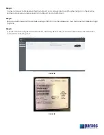
In the router, click on Status, Internet, and then Connections in the dropdown menu.  You should see options related to 

SIM cards installed.  Select the option with a cellular SIM. (Figure 19)

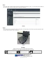
If all of the steps are completed, the antenna should be on and operating. Close the top cover plate using the thread 

forming screws provided in the kit. (Figure 20)

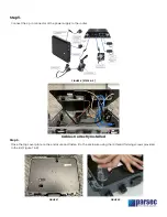
FIGURE 16

FIGURE 17

972-804-4600

Parsec Technologies

[email protected]

Last Revised: 3.9.2021

Summary of Contents for Beagle PRO5B2L2WG-G

Page 1: ...he common European LTE bands with high efficiency The Beagle is optimized for LTE isolation REQUIRED TOOLS REQUIRED ACCESSORIES Phillips Screwdriver 9 Zip Ties Scissors Ethernet Cords 2pc Length as re...

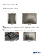
Page 2: ...en the battery tray to the top cover plate using six 6 32 flat head screw provided in the kit Figure 2 Place the router on the top cover plate and align the mount holes of the router with the mounting...

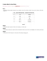
Page 3: ...re 5 Connect the USB connector of the fan to the USB port on the Router Connect the two ethernet cords from the LAN and WAN on the router to the RJ 45 adapters on the antenna enclosure Connect the DC5...

Page 4: ...enclosure and fasten it to the enclosure using the 14 thread forming screws provided in the kit Figure 7 8 FIGURE 7 FIGURE 8 Cables Correctly Installed Step 5 Connect the 4 pin connector of the power...

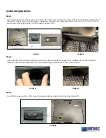
Page 5: ...ry until it is at 100 Turn OFF the AC switch when charging to switch OFF the router Figure 9 10 Open the fan caps on the left and right side of the antenna enclosure Figure 11 12 Make sure that the an...

Page 6: ...ke sure you are connected to a LAN port and not a WAN port Bring up a web browser on the computer and type 192 168 0 1 into the address bar You should see the Cradlepoint login Figure 14 Type the user...

Page 7: ...r general information only It cannot be used as a warranty Parsec Technologies Inc will not accept any liability for any damage caused by an antenna due to unknown variables Make sure the fan cap cove...

Reviews: