Parmco AR 900-CER Installation And Operating Instructions Manual Download Page 24


23 


Installation of this appliance and its connection to the electrical mains must only be 

carried out by authorized personnel. Before any service procedure, it is important to 
ensure that the appliance is DISCONNECTED from the electrical mains. 


Do not modify this appliance. 


After removing the appliance from the packaging, make sure it is undamaged. In the unlikely 
event this occurs, contact Parmco before operating this appliance. 


Make sure that this appliance is adequately ventilated. 


Ensure that the room is well ventilated by keeping the air intakes free of obstruction and in 
good working order, and/or by installing a ventilation extraction system. 


If the appliance is used intensively for a long time, the effectiveness of the ventilation will need 
to be increased, for example, by opening a window or increasing the power of the ventilation 
fan. 

 
NOTES TO THE AUTHORIZED INSTALLER 
 

This appliance shall only be installed by an authorized person. This appliance shall only be installed 
in complete accordance with the Gas and Electrical Standards of New Zealand. All local regulations, 
building code requirements, and all other statutory requirements must be met. 


Data Label 


The data label is located at the rear of the appliance and inside of the utility draw if 
fitted. A duplicate label is supplied for you to adhere to a suitable accessible area next 
to the appliance. The data label on the appliance must NEVER be removed.  


Ventilation 

 
Make sure that this appliance is installed in accordance with the ventilation requirements. 
 
Before any procedure, it is important to check that the appliance is DISCONNECTED from the 
electrical mains. Parmco declines all responsibilities for any damage deriving from installations 
that are in breach of the regulations in force or from failure to comply with these installation 
instructions. 
 

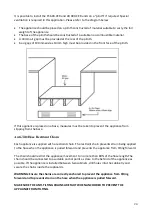
Combustible Surfaces 


The appliance shall be installed in accordance with the New Zealand standards relating 
to the installation of domestic cooking appliances. 
 

In general, any adjoining wall surface within 200mm from the edge of any burner must be of a 
suitable non-combustible material to a height of 150mm, for the entire length of the appliance. 
Any combustible construction (e.g. cabinetry) must be a minimum of 750mm above this appliance. 
If a combustible bench top is within 200mm of any burner, then the appliance top should be a 
minimum of 10mm above the bench top. Any ventilation product supplied by Parmco Appliances 
should be a minimum of 650mm above this appliance. 

Installing Units on a Plinth 


INSTALLATION INSTRUCTIONS 

Summary of Contents for AR 900-CER

Page 1: ...Installation and Operating Instructions Models FS 600 CER FS 600 BKC FS 600 WHC AR 900 CER For your convenience we recommend to attach the serial number label HERE 727626032017...

Page 2: ...by spills when cooking Any breakage or damage of glass items Any damage caused by non recommended product used for cleaning maintaining lubricating or similar Any aspect relating to the installation...

Page 3: ...e take special note of all detailed technical information and installation instructions It is essential that you follow these instructions to ensure the safety and reliability of this appliance Furthe...

Page 4: ...with all the appropriate New Zealand Standards and Regulatory Requirements with particular reference to the New Zealand Electrical and Gas Installation Standards Any attempt to install this or any oth...

Page 5: ...requirements Before cleaning your appliance or perform maintenance always ensure the appliance is disconnected from the main supply Do not repair or replace any part of the appliance unless specifical...

Page 6: ...ve the molten material while the cooking zone is still warm to prevent it from being damaged Failure to instantly clean the ceramic glass could lead to incrustations which are impossible to remove onc...

Page 7: ...mely versatile Steam and Condensation Often owners of new ovens will see a higher level of steam and condensation than they are used to in their previous appliance This is normal and contributes to ke...

Page 8: ...7 Description of appliance AR 900 ceramics FS 600 ceramics PRODUCT DESCRIPTION 900mm 900mm 960mm 5 6 5 7 8 9 5 6 7 8 9...

Page 9: ...heat indicators 4 Cooking mode selection knob 5 Small cooktop element 6 Medium cooktop element Oven and Accessories The appliance is supplied with easy clean shelf supports which offer a range of she...

Page 10: ...9 Controls...

Page 11: ...amic glass has to be cleaned Remove any removable labels and protective sheeting Place a saucepan filled with water on each front hotplates then switch on high power for at least 30 minutes After 30 m...

Page 12: ...ng zones For the inner cooking zone turn the control knob clockwise to the desired position between low and max Once the inner cooking zone is hot the lamp corresponding to the zone illuminates Lowest...

Page 13: ...time you use your appliance set the temperature to MAX and select a cooking mode leaving the empty oven to operate for 30 minutes Then turn off the appliance and allow it to cool Any odours during thi...

Page 14: ...eration Setting If AUTO is flashing automatic or semi automatic program has been set Press the button AUTO will clear from the display and the oven can be operated manually Automatic Setting Automatic...

Page 15: ...arts immediately and AUTO will flash At the finish time reached the oven automatically stops cooking The alarm will ring and AUTO will flash Press the alarm bell to stop the ringing When the button is...

Page 16: ...the exterior of the appliance cool the appliance is fitted with a cooling fan that operates automatically When the oven is on the cooling fan turns on and you will notice a flow of air exiting betwee...

Page 17: ...possible to brown the surface of meats and roasts while locking in the juices to keep them tender Grill can also be used for dishes that require a high temperature on the surface of the dish such as...

Page 18: ...n multi shelves at the same time Baking Results Please note that baking results will vary between different brands of stoves ovens and your usual baking style may need adjusting in order to get the be...

Page 19: ...rses Lasagne 2 190 210 20 25 Sponge Cake 2 3 190 220 25 35 Strudel 1 2 150 25 35 Bread 2 3 190 210 40 Toast 1 2 220 240 7 Grilling First Surface Second Surface Pork Chops 4 7 9 5 7 Fillet of Pork 3 9...

Page 20: ...the oven when it is in operation as this will result in damage to the enamel Clean the glass door using non abrasive products or sponges and dry it with a soft cloth Do not use abrasive cleaners or s...

Page 21: ...eft and right hinge levers A are hooked to part B of the door Dig 4 Reassemble the door by following the above procedures backwards To dismantle the oven door two methods Method 1 remove and assemble...

Page 22: ...turned off before replacing the oven lamp s to avoid the possibility of electric shock Remove the glass cover of the lamp holder as shown below Remove the lamp and replace with a lamp resistant to hig...

Page 23: ...we strongly advise you to contact Parmco Service department specifying the nature of the problem the model and the serial number of the appliance This data is provided on the data label adhered to th...

Page 24: ...ata label is located at the rear of the appliance and inside of the utility draw if fitted A duplicate label is supplied for you to adhere to a suitable accessible area next to the appliance The data...

Page 25: ...rom the base Anti Tilt Hose Restraint Chain Each appliance is supplied with a restraint chain The restraint chain prevents strain being applied to the hose when the appliance is pulled forward and pre...

Page 26: ...d from the oven Should the panels become heavily soiled they will need to be taken out of the oven and cleaned by hand They should be soaked in warm soapy water for at least 2 hours and then wiped cle...

Page 27: ...the oven aligning the holes at the top Refit the side racks by inserting the top of the rack into the holes through the catalytic liner Clip bottom of rack into position over lug Removing and installi...

Page 28: ...m between the contacts the grounding wire should not be interrupted by the switch Before connecting to the mains make sure that The electrical counter the circuit breaker feed cable and socket are sui...

Page 29: ...00 WHC FS 600 BKC 10 7KW AR 900 CER 12 45KW This appliance must be installed in accordance with New Zealand s electrical installation rules and regulations by a suitably qualified and authorized perso...

Reviews: