PARKZONE F4U-1A Corsair Instruction Manual Download Page 8

EN

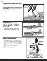
Installing Optional Flaps

1.   Install the left and right flap servos (

A

(PKZ1081 x 2, sold separately) in the wing 
pocket using hot glue or double-sided tape.

2.   Install the control horns (

B

) and plates (

C

) on 

the wing using 2 screws in each horn.

3.  Install a connector and clevis in the second 

innermost hole of the servo arm and outer hole 
of the control horn.

4.   On both flaps, carefully cut a wedge of foam 

from the flap hinge near the aileron hinge (see 
illustration).

5.   On both flaps, carefully cut a small amount 

of foam at the flap and wing root so the flap 
moves freely (see illustration).

6.   Very carefully pull up the tape to place the 

servo wires in the wing channel (

D

).

7.   Place the flap servo wires in the wing channel 

(

D

) with the aileron wires.

8.   Install the flap servo connectors in the holes at 

the wing root on each side.

9.   Place tape over the wing channel (

D

).

10.  Cut a small amount of tape at each flap servo 

arm to let the servo arms move freely.

11.  Attach the servo connectors to the correct 

receiver channels or Y-harnesses.

12.  Proceed to wing installation instructions or 

landing gear installation instructions.

NOTICE:

 Ensure the wires are not crushed or 

damaged when the wing is attached to  
the fuselage.

13.  Do a control test of the flaps using your aircraft 

and transmitter.

A

D

B

C

If you are not installing flaps or retracts, 

please proceed to the Installing the Landing Gear section.

1/2 or Takeoff Flap Full Flaps

Flap down

10mm down

20mm down

Factory Settings

Arms

Horns

Flaps

3 X 15mm (2)

8

Summary of Contents for F4U-1A Corsair

Page 1: ...F4U 1A Corsair Instruction Manual Bedienungsanleitung Manuel d utilisation Manuale di Istruzioni...

Page 2: ...alling Included Optional Belly Tanks 14 Installing Decals 14 Optional Rough Runway Gear 14 Flying Tips and Repairs 15 First Flight Preparation 15 Maintenance After Flying 15 AMA National Model Aircraf...

Page 3: ...hooting guide It s all here so your first flight and every one after is as rewarding as it can be Includes 43 4 oz 1230 g with drop tanks installed 46 6 oz 1320 g with flaps retracts and drop tanks in...

Page 4: ...ays charge batteries away from flammable materials Always inspect the battery before charging and never charge damaged batteries Always disconnect the battery after charging and let the charger cool b...

Page 5: ...ll shine continuously Attempting to charge an over discharged battery will cause the charger to repeatedly flash and beep indicating an error has occurred 9 Always unplug the battery from the charger...

Page 6: ...ransmitter s manual for binding button or switch instructions 8 When the receiver binds to the transmitter the light on the receiver will turn solid and the ESC will produce a series of sounds One lon...

Page 7: ...wer on Transmitter Wait 5 seconds NOTICE Use of CA accelerant on your model can damage the paint DO NOT wipe accelerant from the model instead let the accelerant evaporate 3 X 25mm 2 Arming the ESC Be...

Page 8: ...he wing channel D 7 Place the flap servo wires in the wing channel D with the aileron wires 8 Install the flap servo connectors in the holes at the wing root on each side 9 Place tape over the wing ch...

Page 9: ...m the wing 5 Install the main retracts J in the wing using the 8 screws removed from the landing gear doors and the left and right retract plates 6 Connect the main retracts to the gear harness extens...

Page 10: ...he rear of the fuselage 2 Install the left and right horizontal tails onto the fuselage as shown Ensure the control horn faces down 3 Apply four pieces of tape to the fuselage mounts one on the top an...

Page 11: ...doing the Control Test correctly set the failsafe Make sure the transmitter controls are at neutral and the throttle and throttle trim are in the low position then rebind the model to your transmitte...

Page 12: ...X aircraft transmitter capable of dual rates Adjust according to individual preferences after initial flight High Rate Low Rate Aileron 18mm up down 13mm up down Elevator 20mm up down 16mm up down Rud...

Page 13: ...when removing the screws and the motor from the motor mount Assembly Assemble in the reverse order Notice Correctly align the wire colors and connect the motor to the ESC Make sure the propeller side...

Page 14: ...ould face rearward The wheels project forward from the wing to decrease the possibility of tipping when landing on a rough runway 2 Install the left cover A marked L on the optional left strut B using...

Page 15: ...n to the ground using 1 4 1 3 throttle to allow for enough energy for a proper flare Avoid sharp turns on the ground until the plane has slowed enough to prevent scraping the wingtips The F4U Corsair...

Page 16: ...ws or model demonstrations unless a The aircraft control system and pilot skills have successfully demonstrated all maneuvers intended or anticipated prior to the specific event b An inexperienced pil...

Page 17: ...binding to transmitter Transmitter is too near aircraft during linking process Move powered transmitter a few feet from aircraft disconnect and reconnect flight battery to aircraft Aircraft or transm...

Page 18: ...ct your local distributor or Horizon directly This will enable Horizon to better answer your questions and service you in the event that you may need any assistance For questions or assistance please...

Page 19: ...0 4121 2655 100 service horizonhobby de France Horizon Hobby SAS 14 Rue Gustave Eiffel Zone d Activit du R veil Matin 91230 Montgeron 33 0 1 60 47 44 70 infofrance horizonhobby com China Horizon Hobby...

Page 20: ...demarks of Horizon Hobby Inc DSMX is a trademark of Horizon Hobby Inc registered in the US The Spektrum trademark is used with permission of Bachmann Industries Inc Futaba is a registered trademark of...

Reviews: