


9
GB/IE
Keep out of the reach of children. Store the
product out of the reach of children.
Check the product for damage before each
use. Please do not use this device if you find
that it is damaged in any way.
Check that the screws are tight before each use.
Use the product on a solid, level and intact
surface (e.g. a workbench).
Always disconnect the drill from the power
supply before making adjustments or work
breaks.
The drill stand must be mounted on a work-
bench or a stable, tilt-free table, to ensure a
safe work. Use the drill holes
5
in the base
plate
6
.
Assembly
Note:
You need a 5 mm hexagon key (pro-
vided).
Connect the pillar
7
to the base plate
6
and
tighten the screw to fix the pillar (see Fig. A).
Then fix the slider
9
on the pillar by tightening
screw
12
.
Mount the lever arm
2
onto the slider (see
Fig. B). Tighten the screws as tight as possible.
Mount the vise
13
onto the base plate. To do
this connect the screws with the guide slots
4
in the base plate through the two long slots
14
(see Fig. C).
Note:
The vise can be positioned exactly by
moving the guide slots and long slots.
Mounting the work piece
Hold the quick-release button
16
pressed and
pull the locking device
15
back as far as it goes
(see Fig. D).
Place the work-piece into the vise
13
.
Press the quick-release button and push the
locking device with the clamping jaw
17
against the work-piece.
Tighten the work-piece by turning the locking
device
15
clockwise (see Fig. E).
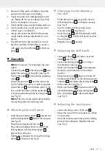
Clamping in and adjusting
the drill
Fit the drill with its clamping collar into the
drill holding fixture
3
and tighten securely
(see Fig. F).
Insert a suitable drill bit into the chuck.
Unscrew screw
12
(see Fig. G).
Move the slider
9
with the clamped in drill
on the pillar
7
, until the drill nearly touches
the work-piece.
Retighten screw
12
securely.
Adjusting the drill depth
Loosen the block
8
and slide it up to the
slider
9
(see Fig. H).
Loosen the locking knob
10
by turning it
anti-clockwise (see Fig. H).
Make sure that the bolt
1
will be released
doing this and slides down to the lowest
position.
Move the lever arm
2
down and read off
the desired drill depth on the drill gauge with
indicator
11
and tighten the locking knob
10
at the same time (see Fig. I).
Make sure the bolt
1
is fixed securely to de-
sired drill depth by tightening locking knob
10
.
Also, fix the block
8
to desire drill depth
(see Fig. I).
Adjusting the work piece
Loosen the fixing screws of the vise
13
.
Adjust the vise with the work piece by sliding
it into position.
Mark the exact position and punch a drilling
point on the work-piece. Retighten the vise
(see Fig. J).


