background image

7

GB/IE/NI

8.12.  After use

1.  Switch off the power tool as described, disconnect it from 

the power supply and Iet it cool down.

2.  Clean and maintain the power tool as described under 

point 10, and store it carefully.

9.  Electrical connection

The electrical motor installed is connected and 
ready for operation. The connection complies with 
the applicable VDE and DIN provisions. The cus-
tomer‘s mains connection as well as the extension 
cable used must also comply with these regula-
tions.

Damaged electrical connection cable

The insulation on electrical connection cables is often dam-
aged.

This may have the following causes:
• Passage points, where connection cables are passed through 

windows or doors.

• Kinks where the connection cable has been improperly fas-

tened or routed.

• Places where the connection cables have been cut due to 

being driven over.

• Insulation damage due to being ripped out of the wall outlet.
• Cracks due to the insulation ageing.
Such damaged electrical connection cables must not be used 
and are life-threatening due to the insulation damage.
Check the electrical connection cables for damage regularly. 
Make sure that the connection cable does not hang on the 
power network during the inspection.

Electrical connection cables must comply with the applicable 
VDE and DIN provisions. Only use connection cables with the 
marking „H05VV-F“.
The printing of the type designation on the connection cable 
is mandatory.

AC motor

• The mains voltage must be 220 - 240 V~ 50 Hz.

• Extension cables up to 25 m long must have a cross-section 

of 1.5 mm

2

.

Connections and repairs of electrical equipment may only be 
carried out by an electrician.

Please provide the following information in the event of any 
enquiries:
• Type of current for the motor
• Machine data - type plate

8.3. Connection to the power supply

1.  Make sure that the power tool is switched off.
2.  Plug the power plug into a correctly installed socket which 

complies with the requirements specified in the technical 
data.

3.  Your power tool is now ready for operation.

8.7. Switching on/off (fig. 8)

To switch on:
Push the on/ off switch (13).

Continuous operation (fig. 8)
Secure the on/off switch (13) with the locking knob (6).

To switch off:
Press the on/off switch (13) briefly and let go.

8.8. Adjusting the oscillation rate (fig. 9)

Before you start working, adjust the oscillation rate according 
to the application. Use a low number of oscillations for rough 
grinding, increase the oscillation rate for fine work.

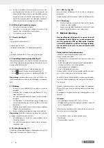
Adjust the oscillation rate by pressing the button (5). 
• Press the 

 button to increase the oscillation rate (fig. 9).

• Press the 

 button to decrease the oscillation rate (fig. 9).

Note: 

The insertion tool moves for a short while after having it 

switched off. Do not put aside the power tool until the insertion 
tool has come to a complete halt.

8.9. Grinding

1.  Attach an appropriate abrasive sheet (16) and select the 

corresponding speed.

2.  Hold the power tool securely at the handle surfaces (7, 2) 

and switch it on as described.

3.  Wait until the insertion tool has reached its full operating 

speed.

4.  Hold the grinding plate (1) as parallel as possible to the 

wall, and touch the surface to be processed with the brush 
edge (A) first.

5.  Apply some pressure to the grinding head (1) such that 

the insertion tool touches the surface to be processed.

6.  Constantly move the power tool over the surface.

Note:

  lf you want to avoid irregular grinding results, do not 

keep the power tool at one spot for too long.

7.  Lift the grinding plate (1) from the surface to be processed 

before switching off the power tool.

8.  Do not put aside the power tool until the insertion tool has 

come to a complete halt.

8.10.  Ceiling grinding (fig. 11)

For working in ceiling area, fix the grinding head with a cotter 
pin (C) (included) as shown in figure 11.

8.11.  LED light (fig. 10)

To ensure a well lit workplace, use the LED light (4) if necessary.
Press the switch (a) to switch ON/OFF the LED light (4).

Summary of Contents for 315148

Page 1: ...struktioner Overs ttelse af den originale driftsvejledning DK IE NI PONCEUSE MURS ET PLAFONDS Consignes d utilisation et de s curit Traduction des instructions d origine FR BE BE DRYWALL SANDER Operat...

Page 2: ...lie end mit allen Funktionen des Ger tes vertraut DE AT CH F r du l ser vend siden med billeder frem og bliv bekendt med alle apparatets funktioner DK Before reading unfold the page containing the ill...

Page 3: ...1 1 2 3 4 6 13 12 11 7 8 9 10 C 19 18 17 15 14 16 5 14 15 10 5 11 12 4 3 2...

Page 4: ...11 14 15 10 6 5 9 B 4 10 7 16 1 A 8 6 13 C...

Page 5: ...que de blessure lisez le mode d emploi NL BE Voordat gebruiksaanwijzing en veiligheidsinstructies te lezen en te observeren GR CY DE AT CH Vor Inbetriebnahme Bedienungsanleitung und Sicherheitshinweis...

Page 6: ...Intended use 2 5 Safety information 2 6 Technical data 5 7 Before starting the equipment 6 8 Attachment and operation 6 9 Electrical connection 7 10 Cleaning maintenance and storage 8 11 Transport 8 1...

Page 7: ...ated dangers The minimum age re quirement must be complied with In addition to the safety notes contained in the present oper ating instructions and the special regulations of your country the general...

Page 8: ...ools that have the switch on invites accidents d Remove any adjusting key or wrench before turning the power tool on A wrench or a key left attached to a rotating part of the power tool may result in...

Page 9: ...s given below Safety instructions for all operations Safety warn ings common for grinding sanding wire brushing polishing or abrasive cutting off operations a This power tool is intended to function a...

Page 10: ...he rotating accessory Ac cessory may kickback over your hand c Do not position your body in the area where power tool will move if kickback occurs Kickback will propel the tool in direction opposite t...

Page 11: ...aused by the grind ing disk edge b Furthermore the brush edge A prevents the generation of excessive dust Dust generated during the grinding pro cess is not transported towards the outside but is remo...

Page 12: ...hed off 2 Plug the power plug into a correctly installed socket which complies with the requirements specified in the technical data 3 Your power tool is now ready for operation 8 7 Switching on off f...

Page 13: ...t Wait until the equipment has cooled down completely Risk of burns 10 1 Cleaning Keep the equipment free of dirt and dust as far as possible Wipe the equipment with a clean cloth or blow it down with...

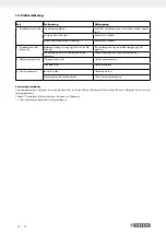
Page 14: ...rator voltage too low Connect power tool to an appropriate power supply 3 Poor operation results Sanding paper worn out Replace sanding paper Abrasive plate worn out Replace abrasive plate by speciali...

Page 15: ...ull and void if any attempt is made to tamper with the device The guarantee is valid for a period of 3 years starting from the purchase date of the device Guarantee claims should be submitted before t...

Page 16: ...11 GB IE NI...

Page 17: ...se 13 5 Sikkerhedsoplysninger 14 6 Tekniske specifikationer 16 7 Inden apparatet tages i brug 17 8 Ops tning og betjening 17 9 Elektrisk tilslutning 18 10 Reng ring vedligeholdelse og opbevaring 19 11...

Page 18: ...endt med de mulige farer ved arbejdet Aldersgr nsen skal overholdes Udover de sikkerhedshenvisninger der er anf rt i denne be tjeningsvejledning samt de srerlige bestemmelser som skai overholdes i Der...

Page 19: ...mhed ved brug af elv rkt jet kan f re til alvorlige kv stelser b B r personligt beskyttelsesudstyr og altid be skyttelsesbriller Brugen af personligt sikkerhedsudstyr s som st vmaske skridsikre sikker...

Page 20: ...ved slyn ges et ukontrolleret elektrov rkt j imod indsatsv rkt jets dreje retning p de blokerede dele g Brug el v rkt j tilbeh r indsatsv rkt j osv i overensstemmelse med disse anvisninger Tag herved...

Page 21: ...retning p det blokerede sted Slibeskiver kan ogs br kke p denne m de Et tilbageslag er resultatet af en forkert eller mangelfuld brug af el v rkt jet Det kan forhindres ved hj lp af egnede sikkerhedsf...

Page 22: ...fig 7 Slibehovedet p dette el v rkt j er omgivet af en b rstekant A Dette giver to fordele a B rstekanten A rager ud over slibepladen 1 og ligger f rst p fladen der skal bearbejdes S ledes bringes sl...

Page 23: ...v udvikling B rsterne bevirker at det st v der opst r ved slibningen ikke kommer udenfor men bortskaffes gennem udsugningssystemet Kontroll r at b rstekanten A er in takt f r hvert arbejde med dette e...

Page 24: ...m f lge af str mst d m Pas p Vent til maskinen er k let helt af Fare for forbr nding 10 1 Reng ring Hold maskinen fri for st v og snavs Gnid maskinen ren med en ren klud eller bl s den over med tryklu...

Page 25: ...meter Str mforsyning f eks generator har for lav sp nding Tilslut el v rkt jet til en egnet str mforsyning 3 D rligt arbejdsresultat Indsatsv rkt jet slidt Udskift indsatsv rkt jet Slibeplade slidt Ud...

Page 26: ...al slitage som f lge af korrekt funktion af apparatet Garantien erkl res ugyldige hvis der g res fors g p at manipulere med enheden Garantien er gyldig i en periode p 3 r fra k bsdatoen af enheden Gar...

Page 27: ...sation conforme 23 5 Consignes de s curit 23 6 Caract ristiques techniques 27 7 Avant de commencer travailler 27 8 Montage et utilisation 27 9 Raccordement lectrique 29 10 Nettoyage entretien et stock...

Page 28: ...ci s sont autoris es travailler avec la machine L ge minimum requis doit tre respect En plus des consignes de s curit contenus dans cette notice et de la r glementation en vigueur dans votre pays vous...

Page 29: ...z les outils lectriques de fa on appropri e N utilisez pas les outils lectriques lorsque vous tes fatigu ou sous l influence de drogues d alcool ou de m dicaments Un seul moment d inattention pendant...

Page 30: ...il l abrasif peut entrer en contact avec des fils lectriques masqu s ou avec le propre c ble d alimentation de l outil lectrique Le contact avec un conducteur d lectricit peut mettre Ies parties m tal...

Page 31: ...c ble d alimenta tion peut tre coup ou happ votre main ou votre bras peuvent alors tre entra n s verse l abrasif en rotation l Ne posez jamais l outil avant l arr t complet de la rotation de l abrasi...

Page 32: ...out destin cette rallonge 12 et verrouillez la comme montr en ill 4 Remarque R glez la ponceuse pour murs et plafonds qui p e de sa rallonge d aspiration 11 de fa on pouvoir travail ler confortablemen...

Page 33: ...pier de verre gros grain pour le pon age grossier et du papier de verre grain fin avec pour Ia finition Nous vous recommandons d utiliser du papier de verre contenant de l oxyde d aluminium du carbure...

Page 34: ...insi vous disposerez constamment de toutes les informations et l ments n cessaires 8 10 Pon age des plafonds ill 11 Pour travailler sur les plafonds bloquez la t te de pon age en position l aide de la...

Page 35: ...ti res recyclables qui peuvent tre mises au rebut dans les d chetteries locales Renseignez vous aupr s de votre mairie ou de l administration municipale concernant les possibi lit s de mise au rebut...

Page 36: ...l outil une source d alimentation appropri e 3 Le pon age n est pas r gulier Le disque abrasif est us Remplacez le disque abrasif Le plateau support de disque abrasif est us Remplacez le plateau suppo...

Page 37: ...e chute ainsi que l usure normale conforme l utilisation Ceciestparticuli rementvalablepourlesaccumulateurspourlesquelsnousoffronstoutefoisunep riodedegarantiede12mois Le droit la garantie dispara t d...

Page 38: ...air gebruik 34 5 Veiligheidsaanwijzingen 35 6 Technische gegevens 38 7 V r ingebruikneming 38 8 Montage en bediening 38 9 Elektrische aansluiting 40 10 Reiniging Onderhoud en opbergen 40 11 Vervoer 41...

Page 39: ...ecteer de vereiste minimumleeftijd Als aanvulling op de veiligheidsvoorschriften in deze handlei ding en de speciale voorschriften van uw land moeten ook de algemeen erkende technische regels voor het...

Page 40: ...rische schok f Als het gebruik van elektrisch gereedschap in een vochtige omgeving onvermijdelijk is ge bruik dan een aardlekschakelaar Het gebruik van een aardlekschakelaar vermindert het risico van...

Page 41: ...af standvan het werkgebied blijven Iedereen die het werkgebied betreedt moet persoonlijke beschermingsmiddelen dragen Fragmenten van het werk stuk of gebroken insteekgereedschap kunnen wegvliegen en...

Page 42: ...n nodig controleren 6 Schakel het elektrische gereedschap uit als het niet wordt gebruikt j Houd het apparaat alleen aan de ge soleerde handgrepen vast wanneer u werkt op plaat sen waar het gereedscha...

Page 43: ...1 Installatie afb 1 3 Klap het voorste en achterste deel samen en draai de vleu gelmoer 3 aan Restrisico s Zelfs als u dit elektrisch gereedschap goed gebruikt blijven er altijd restrisico s De volge...

Page 44: ...de borstelrand A aan op het te bewerken oppervlak 5 Oefen enige druk uit op de schuurkop 1 om het inzet gereedschap op het te bewerken oppervlak te brengen Zuigbuisverlenging monteren afb 4 Steek de...

Page 45: ...onderhoud naar een gekwalificeerde vak man 6 Verplaats het gereedschap met gelijkmatige bewegin gen over het oppervlak Aanwijzing Houd het elektrische gereedschap niet te lang op n plaats om ongelijke...

Page 46: ...het stopcontact 1 Bewaar het elektrisch apparaat buiten bereik van kinde ren op een droge goed geventileerde plaats wanneer het niet wordt gebruikt zoals in een hoge kast of een af sluitbare plek 2 B...

Page 47: ...omvoorziening bijv generator heeft een te lage spanning Sluit het elektrische gereedschap aan een geschikte stroomvoorziening aan 3 Slecht werkresultaat Insteekgereedschap versleten Insteekgereedschap...

Page 48: ...h bij het doelmatig gebruik van het apparaat voordoet Er kan geen aanspraak op garantie worden gemaakt als op het apparaat reeds ingrepen werden uitgevoerd De garantieperiode bedraagt 3 jaar en gaat i...

Page 49: ...44 GR CY 1 45 2 1 11 45 3 45 4 45 5 46 6 49 7 50 8 50 9 51 10 52 11 52 12 52 13 53 14 54 15 67...

Page 50: ...ppach Fabrikation von Holzbearbeitungsmaschinen GmbH G nzburger Stra e 69 D 89335 Ichenhausen VDE0100 DIN 57113 VDE 0113 2 1 11 1 2 3 4 LED 5 6 7 8 9 10 11 12 13 14 15 16 17 18 19 3 1 1 14 6 16 1 18 2...

Page 51: ...46 GR CY 5 m a b c a b c d e f a b c d e f g...

Page 52: ...47 GR CY a b c d e f g a b c d e f g a...

Page 53: ...48 GR CY a b c d a h i j k l m n o p...

Page 54: ...49 GR CY 6 220 240 V 50Hz W 710 S1 n 800 1800 min 1 M 14 225 mm 225 mm II kg 5 2 kg LpA 91 dB A LWA 102 dB A K KpA KWA 3 dB ah DS 3 24 m s K 1 5 m s EN 60745 1 EN 60745 2 3 a b c 1 2 3 4 5 6 a b c...

Page 55: ...50 GR CY 3 8 3 7 16 1 1 16 1 2 16 1 7 8 4 1 5 6 14 15 10 12 5 6 m 8 5 7 A a A 1 b A A 7 H 8 m m 8 1 1 3 3 4 11 12 4 11 8 2 1 2...

Page 56: ...51 GR CY 7 1 8 8 10 11 C 11 8 11 LED 10 LED 4 B LED 4 8 12 1 2 10 9 VDE DIN VDE DIN H05VV F 8 6 1 2 3 8 7 8 13 8 13 6 13 8 8 9 5 9 9 8 9 1 16 2 7 2 3 4 1 A 5 1 6...

Page 57: ...52 GR CY 10 3 m 1 2 11 m 1 2 3 12 220 240 V 50 Hz 25 m 1 5 10 m m 10 1 10 2 10 2 1 1 A 10 2 2...

Page 58: ...53 GR CY 2012 19 13 1 2 3 4...

Page 59: ...003 4003 0 00 Min e mail GR service GR scheppach com e mail CY service CY scheppach com GR CY GEORGE C SOLOMONIDES SON LTD PO BOX 56236 169 LEONTIOS A GR 3305 LIMASSOL CYPRUS www lidl service com QR L...

Page 60: ...em e Verwendung 56 5 Sicherheitshinweise 57 6 Technische Daten 60 7 Vor Inbetriebnahme 60 8 Aufbau und Bedienung 61 9 Elektrischer Anschluss 62 10 Reinigung Wartung und Lagerung 62 11 Transport 63 12...

Page 61: ...orderte Mindestalter ist einzu halten Neben den in dieser Bedienungsanleitung enthaltenen Sicher heitshinweisen und den besonderen Vorschriften Ih res Landes sind die f r den Betrieb von baugleichen M...

Page 62: ...bel die auch f r den Au enbereich geeignet sind Die Anwendung eines f r den Au enbereich geeigneten Verl ngerungskabels verringert das Risiko eines elektri schen Schlages f Wenn der Betrieb des Elektr...

Page 63: ...itsbereich Jeder der den Arbeitsbereich betritt muss pers nliche Schutzausr stung tragen Bruchst cke des Werkst cks oder gebrochener Einsatzwerkzeuge k nnen wegfliegen und Verletzungen auch au erhalb...

Page 64: ...trowerkzeug gegebenenfalls berpr fen 6 Schalten Sie das Elektrowerkzeug aus wenn es nicht be nutzt wird j Halten Sie das Ger t nur an den isolierten Grifffl chen wenn Sie Arbeiten ausf hren bei denen...

Page 65: ...Elektrowerkzeug nicht in feuchtem oder nassem Raum betreiben Das Elektrowerkzeug darf nur in geeigneten R umen gut bel ftet betrieben werden Restrisiken Auch wenn Sie dieses Elektrowerkzeug vorschrif...

Page 66: ...en Sie ab bis das Einsatzwerkzeug zum Stillstand gekommen ist bevor Sie das Elektrowerkzeug ablegen 8 Aufbau und Bedienung m Achtung Vor der Inbetriebnahme das Ger t unbedingt kom plett montieren m Wa...

Page 67: ...nforderungen 8 9 Schleifen 1 Bringen Sie ein geeignetes Schleifblatt 16 an und w h len Sie eine passende Drehzahl 2 Halten Sie das Elektrowerkzeug sicher an den Grifffl chen 7 2 fest und schalten Sie...

Page 68: ...den um Gef hrdungen zu vermeiden Warnung Im Inneren des Elektrowerkzeugs be finden sich keine Teile die vom Benutzer gewartet werden k nnen ffnen Sie das Elektrowerkzeug niemals Bringen Sie es f r wei...

Page 69: ...orgung z B Generator hat zu niedrige Spannung Elektrowerkzeug an eine geeignete Stromversorgung anschlie en 3 Schlechtes Arbeits ergebnis Einsatzwerkzeug verschlissen Einsatzwerkzeug austauschen Schle...

Page 70: ...em Ger t bereits Eingriffe vorgenommen wurden Die Garantiezeit betr gt 3 Jahre und beginnt mit dem Kaufdatum des Ger tes Garantieanspr che sind vor Ablauf der Garantiezeit innerhalb von zwei Wochen na...

Page 71: ...66 DE AT CH...

Page 72: ...vljuje da postoji sukladnost prema EU smjernica i normama za sljedece artikle RS potvr uje slede u uskla enost prema smernicama EZ i normama za artikal RO declar urm toarea conformitate corespunz tor...

Page 73: ......

Page 74: ......

Page 75: ......

Page 76: ...BH G nzburger Str 69 D 89335 Ichenhausen IAN 315148 6 Last Information Update Tilstand af information Version des informations Stand van de informatie Stand der Informationen Update 12 2018 Ident No 3...

Reviews: