background image

21

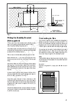
LEVELLING FEET

PENCIL LINE ON THE FLOOR

PLAN VIEW OF THE COOKER

580 mm.

100 mm.

300 mm.

295 mm.

WALL FACE

A

BACK OF COOKER

SIDE VIEW

OF THE COOKER

BASE OF COOKER

ENGAGEMENT EDGE FOR

STABILITY BRACKET

Fig. 8

Fitting the Stability Bracket
(Not supplied)

If the cooker has to be installed with a flexible supply

pipe, it is necessary that a stability device is fitted.

(See "Important Safety Requirements").

If a stability bracket should be fitted by the installer, these

instructions should be read in conjunction with the leaflet

packed with the stability bracket.

Place cooker in its intended position and level cooker.

Mark off 295mm (11 

1

/

2

") from the right hand side of the

cooker as shown, this is the centre line of the bracket

fixing.

Draw a line 100mm (4") from the front edge of the levelling

feet (see Fig. 7) and remove cooker from its position.

Mark off 580mm (23") back from this line on the centre

line of the bracket to locate the front edge of the lower

bracket.

Fix lower bracket (with two fixing holes) to the floor, then

measure height from floor level to engagement edge on

back of cooker, dimension 'A' of Fig. 7.

Assemble  upper  bracket  to  lower  bracket  so  that

underside of bracket is dimension 'A' +3mm (1/8") above

floor level. Re-position cooker and check that top bracket

engages into cooker back to a depth of 75mm (3"), as

shown in Fig. 7.

Should the stability bracket currently installed not allow

the cooker to stand correctly, ask the installer to replace

it with the correct type.

Fig. 7

Connecting to Gas

This cooker is designed to be installed with an appliance

flexible connection. Connection is made to the RC 1/2

(1/2" B.S.P.) threaded entry pipe located just below the

hotplate level on the rear right-hand side of the cooker.

Check for gas soundness after connecting the gas supply.

The gas bayonet connector must be fitted in the shaded

area indicated in Fig. 8. Take into account that it must

be possible to pull the cooker forward sufficiently. The

hose must not get caught on the stability bracket.

Note:

If using different types of gas bayonet connection, it may

not be possible for the appliance to be pushed fully back

to the wall stops.

Important:

Flexible  tubing  MUST  comply  with  BS.669  Current

Edition.

FO  0179

FO  0180

600

450

130

All manuals and user guides at all-guides.com

all-guides.com

Summary of Contents for SIM 333

Page 1: ...MIXED FUEL COOKER SIM 333 Please read this instruction booklet before using the appliance INSTRUCTION BOOKLET GB i All manuals and user guides at all guides com a l l g u i d e s c o m...

Page 2: ...ot surfaces of the cooker l Unstable or misshapen pans should not be used on the hob burners as unstable pans can cause an accident by tipping or spillage l Never leave the cooker unattended when cook...

Page 3: ...Description of the Cooker Splash back Semi Rapid burner Rapid burner Control panel Shelf Ovendoor Semi rapid burner Auxiliary burner Storage drawer Important Safety Information 2 Description of the Co...

Page 4: ...Panel 1 Electric ignition push button 2 Back left burner control knob semi rapid 3 Front left burner control knob rapid 4 Front right burner control knob auxiliary 5 Back right burner control knob sem...

Page 5: ...d size the flame will spread beyond the bottom of the pan causing the handle to overheat As soon as a liquid starts boiling turn down the flame so that it will barely keep the liquid simmering Take ca...

Page 6: ...3 Turn the thermostat control knob clockwise to select temperatures between 50 C and 250 C max Mains on Light The mains on light will come on when the oven function control knob is set Thermostat Cont...

Page 7: ...er and in accordance with existing rules and regulations The relevant instructions are to be found in the second section of this manual Please ensure that when the appliance is installed it is easily...

Page 8: ...ansmit heat to the food inside them A Aluminium earthenware oven glassware and bright shiny utensils reduce cooking and base browning B Enamelled cast iron anodized aluminium aluminium with non stick...

Page 9: ...al requirements Cooking Chart Food Shelf Cooking Position Temp C Biscuits 180 190 Bread 210 220 Casseroles 130 140 Cakes Small and queen 160 170 Sponges 160 170 Madeira 140 150 Rich Fruit 130 140 Chri...

Page 10: ...roasting ensure the meat is cooked thoroughly use a meat thermometer if preferred to check the centre temperature has reached the required temperature see table below Roasting Chart to adjust the tem...

Page 11: ...at and poultry up to 2 kg 4 lb are suitable for defrosting in this way Refer to the following table for approximate defrosting times The times quoted in the chart should be used as a guide only as the...

Page 12: ...e grid in the grill pan to allow maximum circulation of air to lift the food out of the fats and juices Food such as fish liver and kidneys may be placed directly on the grill pan if preferred Food sh...

Page 13: ...washer proof If washing them by hand take care when drying them as the enamelling process occasionally leaves rough edges If necessay remove stubborn stains using a paste cleaner The pan support of th...

Page 14: ...temperature 300 C having the following characteristics Voltage 230 240V 50Hz Power 15W Connection E14 Cleaning the Oven The oven should be kept clean at all times A build up of fats or other foodstuf...

Page 15: ...ticles u Check the burner cap and crown have been replaced correctly e g after cleaning u Check that both a cooking function and temperature have been selected u Check the oven is wired in properly an...

Page 16: ...ter you and your appliances France Senlis 33 0 3 44 62 20 13 Germany N rnberg 49 0 800 234 7378 Italy Pordenone 39 0 800117511 Sweden Stockholm 46 0 20 78 77 50 UK Slough 44 0 1753 219898 Parkinson Co...

Page 17: ...erth PH1 3AF SHETLAND 3 4 Carlton Place Lerwick Shetland OWN SALES ZE1 0PW SHETLAND Bolts Shetland 26 North Road Lerwick OWN SALES Shetland ZE1 0PE WHALSAY Leask Electrical Harisdale Symbister Whalsay...

Page 18: ...DA11 0DL IPSWICH Unit 6C Elton Park Business Centre Hadleigh Road Ipswich IP2 0DD LETCHWORTH 16 17 Woodside Ind Park Works Road Letchworth Herts SG6 1LA LONDON 2 4 Royal Lane Yiewsley West Drayton Mi...

Page 19: ...ructions for the Installer Hob Rear left burner semi rapid 2 0 kW Front left burner rapid 3 0 kW Rear right burner semi rapid 2 0 kW Front right burner auxiliary 1 0 kW Oven Convection Heating Element...

Page 20: ...the floor covering in the area below the cooker is either securely fixed so as not to ruck up when the cooker is moved or if preferred removed Important Safety Requirements This appliance must be ins...

Page 21: ...o engagement edge on back of cooker dimension A of Fig 7 Assemble upper bracket to lower bracket so that underside of bracket is dimension A 3mm 1 8 above floor level Re position cooker and check that...

Page 22: ...to the terminal in the plug which is marked with the letter E or the earth symbol or coloured green and yellow Connect the blue neutral wire to the terminal in the plug which is marked with the lette...

Page 23: ...rner supply The pressure reading should be nominally 20mbar and must be between 17 mbar and 25mbar Turn off the burner supplies Conversion from Natural Gas to LPG It is important to note that this mod...

Page 24: ...Electrolux Group is the world s largest producer of powered appliances for kitchen cleaning and outdoor use More than 55 million Electrolux Group products such as refrigerators cookers washing machine...

Reviews: