


Parker Hannifin S.p.A. - Divisione S.B.C. “SPD” User’s Manual
22
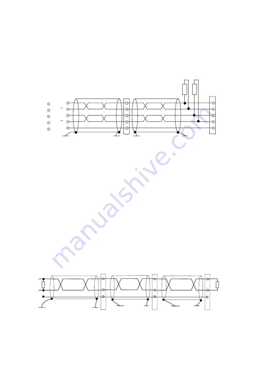
A line closing 180 Ohm resistance should be connected between A /A and B /B. If several
input ports are connected in parallel, this operation must be carried out only on the last unit in
the chain.
Connecting to the electrical shaft
1
2
3
4
7
DRIVE
slave
DRIVE
slave
master
A
A
B
B
GND
1
2
3
4
7
DRIVE
180 ohm
In the example given above, the connection of two SPD to the electrical shaft with a master is
shown, but the diagram could be extended to several converters respecting the series
connection. The line charge resistors must be connected to the last converter. The master can
be an encoder powered externally or an encoder simulator of another converter.
The signal of the master encoder must in any case be of differential type 5V RS-422.
Therefore, it is possible to connect a maximum of ten slave SPD.
If the master is a SPD type converter, you can connect up to 32 converters to the electrical
shaft by using the same signal of the simulated encoder (standard RS-422).
For the relevant programming, refer to paragraph
Electric shaft + positioner
described in
section “Operating modes” of this manual.
4.4.6 CANBUS
connection
A CanBus interface based on the physical layer ISO/DIS11898 is included on the SPD
converter. The Data link layer is the full CAN version 2.0 part A (ID 11 bit) and a subset of
the application layer SBCCAN is used. The termination resistance on the last drive must be
connected externally.
Master
Can-bus
Can connector
NODE 1
2
7
CANL
CANH
120
NODE "n"
2
7
LAST NODE
120
7
2
CAN_GND
3
3
3


