


8
Parker Hannifin
Pump and Motor Division
Trollhättan, Sweden
Service Manual
Series V14
Bulletin HY30-5510-M1/UK
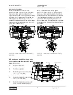
Motor installation
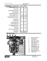
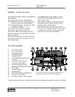
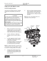
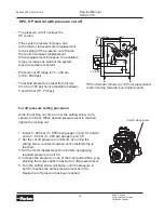
Direction of rotation
The V14 motor is bi-directional. Fig. 1
shows shaft rotation vs. direction of flow.
When the A port is pressurized (black ar
-
row) the motor turns counter clockwise (left
hand, L, rotation), and when the B port is
pressurized (open arrow) the shaft turns
clockwise (right hand, R, rotation).
Note:
Before installing the V14 in series
(when the A and B ports can be subject to
high pressures simultaneously) contact Par-
ker Hannifin (Mobile Controls Div.).
Filtration
Maximum motor service life is obtained
when the fluid cleanliness meets or ex
-
ceeds ISO code 18/13 (ISO 4406).
A 10 µm (absolute) filter is recommended.
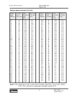
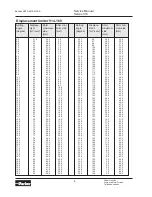
Case pressure
The lowest and highest recommended case
pressure (V14 with shaft seal type
H or V
)
at selected shaft speeds is shown in the
table below.
The min case pressure secures sufficient
lubrication, and the max case pressure,
which secures nominal seal life, should be
measured at the drain port.
Note:
Contact Parker Hannifin (Pump and
Motor Div.) for information on other shaft
seals.
Size
1500 3000 4000 5000 6000
V14-110
max 10 1-6 1.5-5 2-4.5
-
Min and max case pressure [bar] vs. shaft speed
[rpm].
V14-160
max 10 1-6 2-5.5 2.5-5.5 -
Required inlet pressure
The motor operates as a pump under cer-
tain conditions. When this occurs, a mini-
mum pressure must be maintained at the
inlet port. Increased noise and gradually
deteriorating performance due to cavitation
may otherwise be experienced.
A 15 bar inlet pressure, measured at the
motor inlet port, satisfies most operating
conditions.
Contact Parker Hannifin (Mobile Controls
Div.) for more specific information on inlet
pressure requirements.
Operating temperatures
The following temperatures should not be
exceeded (type
H
shaft seal):
Main circuit: 80 °C
Drain fluid: 100 °C
FPM shaft seals (type
V
) can be used to
115 °C drain fluid temperature.
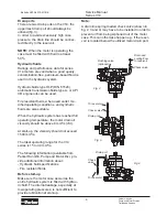
Continuous operation at high power levels
usually requires case flushing in order for
the fluid to stay above the minimum visco
-
sity requirements.
A flushing valve and restricting nozzle, av
-
ailable as an option, provide the necessary
main circuit flushing flow.
Refer to fig. 2 (next page).
Note:
For high speed info, see Marketing
information database.
Port
A
Port
B
Left hand
(counter clockwise)
rotation (L)
Right hand
(clockwise)
rotation (R)
Fig. 1 (motor rotation vs. direction of flow).