40
41
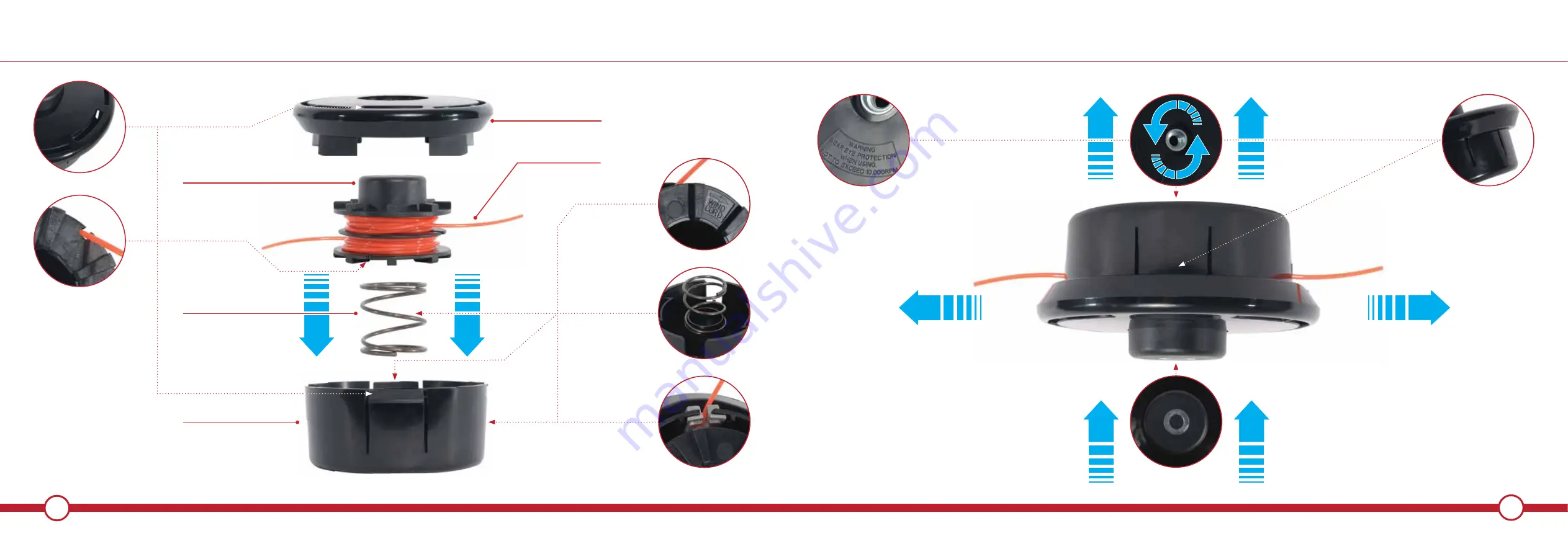
OPEN & REPLACE SPOOL LINE
OPEN & REPLACE SPOOL LINE
SPOOL COVER
SPOOL CARTRIDGE
SPOOL LINE
SPOOL SPRING
SPOOL BODY
BUMP TO FEED LINE
LINE FEED DIRECTION
LINE FEED DIRECTION
PUSH TO UNCLIP
WEAR EYE PROTECTION
TURN ANTI-CLOCKWISE TO ATTACH TO HUB


