IQAN-MC31Instruction book
Publ no HY33-8411-IB/UKEdition 2016-07-05
Page 1: ...IQAN MC31 Instruction book Publ no HY33 8411 IB UK Edition 2016 07 05...
Page 2: ...nectors C1 C4 11 Supply voltage 15 Addressing terminating 16 Diagnostic interfaces 17 Reference voltage VREF 18 Voltage inputs 19 Digital inputs 22 Frequency inputs 24 Proportional outputs 25 Connecti...
Page 3: ...is common to the term hazardous situation that a person is exposed to a hazard As a way of pointing out important information for the machine designer that in some way relates to safety This includes...
Page 4: ...ation contains product information in a compact format for details on the information found in those documents consult this manual The IQAN module documentation system Compact Documentation Main Docum...
Page 5: ...ctions on the system must be disconnected from other equipment The negative cable must always be disconnected from the battery before disconnecting the positive cable The ground wire of the welder sha...
Page 6: ...ics may only be carried out by trained personnel who are well acquainted with the control system the machine and its safety regulations Before you start Read section Start up Additional information fo...
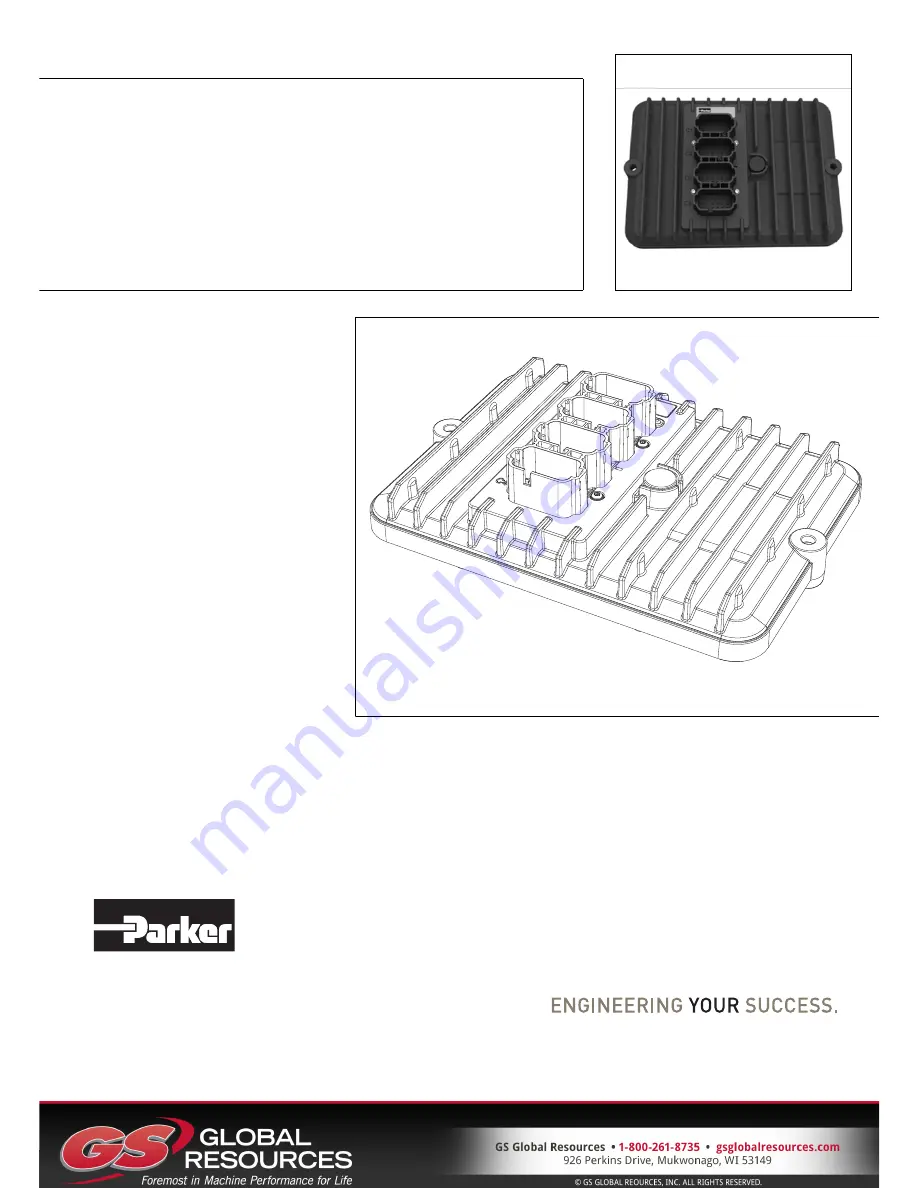
Page 7: ...n there is a need of higher performance in a sub circuit or when there is an OEM supplied overall machine master This product is designed for the outdoor environment and comes with an IP6K9K protectio...
Page 8: ...ferent modes Either Current mode current closed loop or PWM mode voltage open loop signals can be selected and the parameters configured using IQAN software See below In order to increase the performa...
Page 9: ...unit has four 4 CAN buses CAN A thru CAN D The buses may be configured using IQAN software to be ICP ICP IQAN CAN Protocol SAE J1939 or Generic user defined CAN protocol e g CANopen Communication The...
Page 10: ...8 Markings Approvals 3 Product description Instruction book IQAN MC31 Markings Approvals...
Page 11: ...r an application defined error value for the module inputs and the module outputs will be off The error will be presented on the master display module if there is one and with a related blink code on...
Page 12: ...act is avoided e g impact from falling objects or the module being used as a step Locate the module so that air can circulate to eliminate excess heat Ensure that no external heat e g from the engine...
Page 13: ...GH in dominant state CAN B L 5 CAN low voltage bus line will be LOW in dominant state CAN B H 6 CAN high voltage bus line will be HIGH in dominant state ADDR L 7 IdTag interface Low side to address ta...
Page 14: ...e for external sensors Return 0V VREF A 2 Voltage reference for external sensors Sourcing 5V VIN A 3 I Voltage signal input VIN B 4 I Voltage signal input VIN C 5 I Voltage signal input VIN D 6 I Volt...
Page 15: ...nce for external sensors Sourcing 5V DIN A 3 I DIN FIN DFIN PCN DPCN signal input DIN B 4 I DIN FIN DFIN PCN DPCN signal input DIN C 5 I DIN FIN DFIN PCN DPCN signal input DIN D 6 I DIN FIN DFIN PCN D...
Page 16: ...ver low side CRET A 3 O COUT power driver low side COUT B 4 O COUT power driver high side CRET B 5 O COUT power driver low side CRET B 6 O COUT power driver low side COUT C 7 O COUT power driver high...
Page 17: ...r should be as close to the battery as possible for safety IQAN expansion modules do not have RTC WARNING Risk of injury To reduce the risk for uncontrolled supply of an IQAN master module i e a short...
Page 18: ...ore information please refer to the IQANdesign user manual It is the combination of address and type that gives each master module a unique identification The maximum number of MC31 addresses is 8 den...
Page 19: ...to use this feature Contact Parker for information about supported CAN interfaces A termination resistor is usually required at the CAN interface on the PC Parker part number 5030082 or 5030182 or an...
Page 20: ...ors and potentiometers VREF positions NOTICE It is strongly recommended to use the module s VREF and VREF to all sensors and potentiometers that are connected to the module inputs This will reduce bad...
Page 21: ...on NOTICE The negative terminal of the sensor must not be connected to the chassis Maximum load for VREF position see Appendix A Connecting other 3 wire sensors The same type of connection shown for p...
Page 22: ...d be connected to VREF and VIN DIN respectively for 5V signal The current consumption for the input is negligible NOTICE Maximum load for VREF position see Appendix A EXAMPLE Connect the negative term...
Page 23: ...ed to connect system voltage BAT to the input through a switch in order to reserve 5Vdc VREF for sensors and potentiometers EXAMPLE Connect the positive and negative terminals of the switch to supply...
Page 24: ...ing switches to the digital inputs DIN that share pins with CRET extra precautions should be taken WARNING The DIN that share pins with the CRET positions of the proportional outputs have a possibilit...
Page 25: ...4 Vdc systems The DIN signal will not be detected by the module Remember that these flexible I O pins must be configured in pairs of the same type EXAMPLE Connect the supply of the switch to BAT throu...
Page 26: ...e terminal to the VREF respectively The sensor signal is connected to the FIN position If the current consumption for the sensor exeeds the maximum load for the VREF the sensor could be connected to t...
Page 27: ...e frequency which can be changed using IQAN software For the possible frequencies see Appendix A Connecting loads to proportional outputs Connecting a load e g one proportional valve section to the cu...
Page 28: ...ut and ground as close to the load as possible This protects the output against high voltage transients For example use diode 1N5408 3A 1000V Depending on the load other clamping diodes might be used...
Page 29: ...ents For example use diode 1N5408 3A 1000V Depending on the load other clamping diodes might be used instead WARNING Loads on DOUT with Low Side switch DOUT LS must always be controlled on the high si...
Page 30: ...might be used instead DOUT output diagnostics The diagnostic DOUT is capable of detecting internal faults as well as wiring faults The fault will be identified as one of the following status values in...
Page 31: ...a tively the emergency stop may also shut off the diesel engine or a dump valve and with that depressurize the hydraulic system Prepare for system start WARNING Make sure no one is in dangerous proxim...
Page 32: ...the IQAN module will indicate error status through the red blinking LED This gives an immediate diagnosis as to the nature of the error that has occurred The location of the LED indicators on the IQA...
Page 33: ...he application will not be loaded This is a special start up mode that is used for master modules and puts the unit in a safe state without starting any application When safe mode is desired a jumper...
Page 34: ...ate Heat operation Heat storage Cold Change of temperature IEC 60529 2001 IP67 DIN 40050 Part 9 1993 IP6K9K IEC 60068 2 52 1996 Kb 72 h IEC 60068 2 30 2005 Db 55 C 95 RH 6 cycles IEC 60068 2 78 2001 C...
Page 35: ...25 mV C 40 to 85 C Maximum load current 140 mA on each VREF Protection overload SCB SCG Diagnostics over under voltage Under over voltage threshold 150 mV from nominal value Signal input VIN Number of...
Page 36: ...V 0 3 V Input impedance 6 8 kohm in parallel with 10 nF Sample rate same as system cycle time TSC Maximum continuous voltage 32V Diagnostics Defined in application Signal input PCNT DPCNT Number of PC...
Page 37: ...BAT 14V and FDITH 200 Hz 5 ohm 10 mH 5 ohm 20 mH 10 ohm 30 mH 20 ohm 60 mH Maximum allowable load inductance 1 0 A load 1 5 A load 2 0 A load 500 mH 200 mH 50 mH Protection SCB SCG Diagnostics Operati...
Page 38: ...typ 0 41 V 1 5 A load Leakage current in OFF state DOUT A to C high side DOUT D to E high side DOUT F to H low side DOUT I to J low side 100 A 100 A 2 mA 100 A Maximum allowable load inductance DOUT...
Page 39: ...ease safety WARNING Don t use the machine if an error message or error code is activated LED indicator showing different MC31 modes Status Flash yellow Normal operation Application not loaded No appli...
Page 40: ...he IQAN MC31 module Appendix C Instruction book IQAN MC3 Appendix C Dimensioning of the IQAN MC31 module 6 12 18 6 12 18 6 12 18 6 12 18 1 7 13 1 7 13 1 7 13 1 7 13 A B C D C4 C3 C2 C1 IQAN MC3 230 21...
Page 41: ...nge without notice Parker Hannifin Electronic Controls Division SE 435 35 M lnlycke Sweden Tel 46 31 750 44 00 Fax 46 31 750 44 21 www parker com Parker Hannifin Electronic Controls Division 1651 N Ma...