

2
Bulletin HY11-5715-621
Parker Hannifin Corporation
Hydraulics Group
ASEW 001D10D11 5715-621.indd CM 08.12.11
Installation
Instructions for use
•
Connection leads to the limit switch are to be routed separately from
the main current cables, e.g. cables to the electric motors or solenoids,
as otherwise inductive voltage peaks can reach the limit switch via the
power supply network, and damage them in spite of the integrated safety
circuit.
• Suitable DC supply is necessary as power supply to the limit switch. The
residual waviness of the feed voltage must not exceed max. 10%.
• Switch-off voltage peaks when switching inductive loads are to be de
-
creased using corresponding safety circuits, e.g. recovery diodes.
• An integrated overload safety circuit interrupts the switching function of
the limit switch in the case of overload. The limit switch is then automati
-
cally ready again after the duration of the overload state.
• The limit switch may not be installed in the vicinity of AC-operated con
-
sumers, e.g. AC solenoids, as otherwise malfunctions can occur. In any
case, a minimum clearance of 0.1 m must be observed.
• Only operation within the stated technical data is allowed.
• Connections must be made according to the connections diagram.
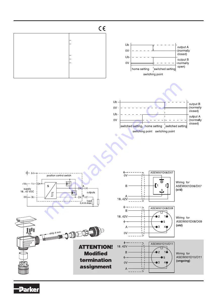
This switch is dedicated for the supervising of ONE trip point. When the
trip point is reached, the output A (pin 4) is non conducting, this means
a NORMALLY CLOSED function. Simultaneously the output B (pin 2)
becomes conducting, this means a NORMALLY OPEN function.
This switch is dedicated for the supervising of the neutral position of a
vale spool and is equipped with two trip points, operated by a movement
from within the neutral position. In this case the output A (pin 4) beco-
mes non conducting, this means a NORMALLY CLOSED function. If
the movement from the neutral position goes in the opposite direction,
the output B (pin 2) is non conducting, this means also a NORMALLY
CLOSED function.
Characteristics Data
Limit switch type ASEW001 D10
Wiring
Limit switch type ASEW001 D11
Installation guide
Position control switch
Series ASEW 001 D10/D11
Feed voltage range
18 ... 42VDC
Waviness of the feed voltage range
<10%
Current consumption without load
<30mA
Max. output current per channel, ohmic 400mA
Min. output load per channel, ohmic
100kOhm
Max. output drop at 0.2A load
<1.1V
Max. output drop at 0.4A load
<1.6V
Switching hysteresis
<0.1mm
Ambient temperature range
0...50°C
Max. tol. ambient field strength at 50 Hz 1200A/m
Protection
IP 65
Socket
M12 to IEC 61076-2-101
Connection Diagram
Note: Required leakage values of hydraulic DC safety gate valves
for injection moulding machines may be asked at Parker (infohcd@
parker.com).
The setting of the position control switch adjusted in
the factory may not be changed.


