


Chapter 2, ACR8010 Motherboard Hardware Set-Up
25
ACR8010 MOTHERBOARD JUMPERS
RS-422/485 Configuration Jumpers, continued
These jumpers selections show some of the standard interface configurations for the
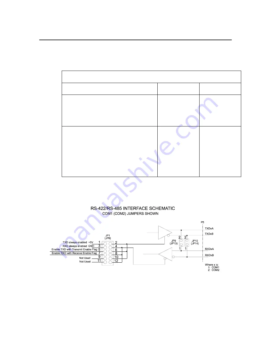
RS-422/RS-485 output control. Refer to the following figure for a schematic of the
RS-422/RS-485 interface.
Standard RS-422/485 Interface Jumpers Examples
Interface Function
COM1 Jumpers
COM2 Jumpers
RS-422 Full Duplex:
Drivers and Receivers are enabled
at all times.
4-Wire Interface.
JP1-1 to JP1-2
JP1-3 to JP1-4
JP9 Out
JP10 Out
JP6-1 to JP6-2
JP6-3 to JP6-4
JP13 Out
JP14 Out
RS-485 Half Duplex:
Drivers and Receivers are enabled
and disabled by the user via
COM1/COM2 RXD/TXD
Transmit Enable flags.
2-Wire Interface.
JP1-1 to JP1-2
JP1-3 to JP1-4
JP9 In
JP10 In
JP6-1 to JP6-2
JP6-3 to JP6-4
JP13 In
JP14 In
Table 2.9
ACR8010 RS-422/485 Interface Jumpers
Refer to Figure 1 for jumper location.
Figure 4.
ACR8010 RS-422/RS-485 Interface Schematic
Artisan Technology Group - Quality Instrumentation ... Guaranteed | (888) 88-SOURCE | www.artisantg.com


