


English
1-8
Set-Up Instructions
Select the application mode. See Chapter 9 for the application description.
Press (M) until F100 is shown on the display
Press (O) until only the FWD LED is illuminated (X O X X)
Press (UP) to access parameter block F2xx
Press (O) until both the FWD and DGT LEDs are illuminated (X O O X)
Press (UP) until display shows F228
Press (E) to edit the application number
Use the (UP) and (DOWN) keys to select the application
Press (E) to confirm your selection
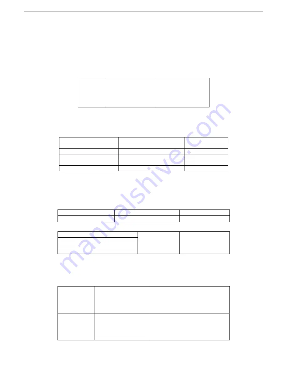
F228
Application selection
0: Invalid
1: Basic speed control
2: Auto/manual control
3: Stage speed control
4: Terminal control;
5: PID control;
Application is set as default, this allows access to all paramaters please see the full manual for
description on all operations.
For application connection drawings please see the end of this quick start guide.
Set the Motor Paramaters
F801 Rated power (kW) Setting range: 0.75
~
1000
F802 Rated voltage (V) Setting range: 1
~
440
F803 Rated current (A) Setting range: 0.1
~
6500
F804 Number of motor poles Setting range: 2
~
100
4
F805 Rated rotary speed Setting range: 1
~
30000
F810 Motor rated frequency Setting range: 1.0~590.0
50.00
Select control mode
The AC10 inverter has three control modes: sensorless vector control (F106=0), VVVF control (F106=2)
and vector control 1 (F106=3). Under VVVF control mode, theAC10 inverter has four kinds of torque
compensation modes: Linear compensation (F137=0); Square compensation (F137=1); User-defined
multipoint compensation (F137=2); Auto torque compensation (F137=3)
Set the limits
F111 Max Frequency (Hz) Setting range: F113
~
590.0
Mfr’s value: 50.00
F112 Min Frequency (Hz)
Setting range: 0.00
~
F113
Mfr’s value: 0.50
Set the ramp rates
F114 First Acceleration Time (S)
Setting range:
0.1
~
3000
Mfr’s value: subject to
inverter model
F115 First Deceleration Time (S)
F116 Second Acceleration Time (S)
F117 Second Deceleration Time (S)
Set the I/O control mode
The channel for inverter to receive control commands (including start, stop and jogging, etc) contains 5
modes: 0. Keypad control; 1. Terminal control; 2. terminal control 3. Modbus control; 4. Keypad
+ teModbus. The modes of control command can be selected through the function codes F200
and F201.
F200
Source of start command
0: Keypad command;
1: Terminal command;
2: Keypad
+
Terminal;
3: MODBUS;
4: Keypad
+
Terminal
+
MODBUS
F201
Source of stop command
0: Keypad command;
1: Terminal command;
2: Keypad
+
Terminal;
3: MODBUS;
4: Keypad
+
Terminal
+
MODBUS
This manual was downloaded on www.sdsdrives.com
+44 (0)117 938 1800 - [email protected]
Summary of Contents for AC10 series
Page 61: ...8 4 This manual was downloaded on www sdsdrives com 44 0 117 938 1800 info sdsdrives com...
Page 69: ...10 2 This manual was downloaded on www sdsdrives com 44 0 117 938 1800 info sdsdrives com...
Page 70: ...10 3 This manual was downloaded on www sdsdrives com 44 0 117 938 1800 info sdsdrives com...
Page 71: ...10 4 This manual was downloaded on www sdsdrives com 44 0 117 938 1800 info sdsdrives com...
Page 72: ...10 5 This manual was downloaded on www sdsdrives com 44 0 117 938 1800 info sdsdrives com...


