


2
Refrigerating Specialties Division
In addition to the standard "P" or "3P" version, other
regulator variations can be combined along with the
pneumatic variation to perform more than one control
function. For example, A4ADP dual pressure regula-
tor has the ability to revert to a high pressure setting
via its high pressure pilot when the pilot solenoid is
de-energized. The fluid temperature range for the A4
Series of Regulators is -50F to 220F (-45C to 105C).
Important Note:
The control air supplied to the regulator must be
clean, dry and oil free. To avoid the possibility of rust
and of moisture from the compressed air freezing in
the bonnet or in other parts of the control system,
dehydrated air must be used whenever it may come
in contact with temperatures below freezing. For
applications where temperatures are below 32F (0C),
the Type A4AR main valve with a remote pneumatic
pilot should be used. Thus the pilot can be located in
a nonrefrigerated space, connected to the main valve
by a pair of 3/8" (9 mm) pilot control lines.
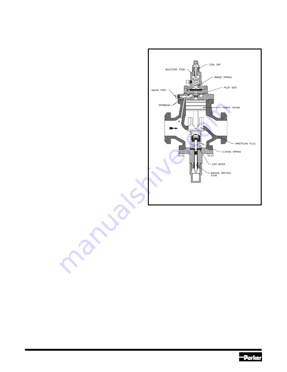
Principles of Operation (See Fig.1)
The principles of operation are the same as the basic
A4A regulator except the set-point of the regulator is
compensated or re-adjusted by the pneumatic
pressure fed into the valve bonnet.
The inlet refrigerant pressure enters the space under
the diaphragm through passage N. When the force
created by the pressure exceeds the combined forces
of the pneumatic pressure in the bonnet and the
range spring force, the diaphragm is lifted off the pilot
seat allowing pressure to enter on top of the power
piston. This causes the power piston to move down-
ward forcing the modulating plug to open and modu-
late to maintain the varying set-point as dictated by
the pneumatic control pressure communicated to the
valve bonnet. An increase in refrigerant inlet pres-
sure, above the varying set-point pressure setting,
lifts the diaphragm further, allowing more pressure on
top of the power piston and opening the valve wider.
A decrease in inlet refrigerant pressure, below the
varying set-point pressure setting, causes the dia-
phragm to move closer to the pilot seat reducing the
pressure on the top of the power piston and causing
the closing spring to reduce the valve opening. The
pressure on top of the power piston is controlled by
the flow through the pilot seat and the bleed off
through the bleed hole in the power piston and
through the clearance between the piston and body
bore. A minimum of 2 psi (0.14 bar) pressure differ-
ence across the valve is required to open fully.
The A4AP/A4A3P Pressure Regulator therefore
opens on a rise in the inlet pressure above the set-
point and closes on a drop in inlet pressure below the
set-point. The inlet pressure is not appreciably affected
by variations in the outlet pressure.
Manual Opening Stem:
All Type A4A Regulators are provided with a manual
opening stem. To open the regulator manually, back
the stem out (turn counter-clockwise) until it stops.
To put the regulator into automatic operation, turn the
stem in (clockwise) until only the flats on the stem
protrude from the packing nut.
Adjustment
Adjust the controller according to the manufacturers
instructions and set it for the desired sensitivity. This
sensitivity setting depends on the amount of regulator
inlet pressure change necessary to counteract the
load change to keep the temperature at the thermo-
stat within the desired limits.
To adjust the pressure regulator, disconnect the air
line and proceed as follows: Install an accurate
pressure gauge in the gauge port. Back the pressure
adjusting stem out to its stop (counter clockwise).
This will reduce the set-point to its lowest level and
cause the valve to open wide. Start the system, and
when suction pressure is about the desired pressure,
Fig. 2 A4A3P


