


Refrigerating Specialties Division
3
Disassembly and Assembly
Refer to the exploded views (Fig. 2) for the parts discussed in this section.
Before disassembling or assembling an A2 regulator read the information
in this bulletin and Bulletin RSB, Safety Procedures for R/S Refrigeration
Control Valves.
Before a regulator Is removed from the line or disassembled in the line,
make sure that all refrigerant has been removed from the regulator
(including the bonnet where applicable), and the regulator is isolated from
the rest of the system in a safe manner.
All A2 Regulators, General Procedure
Disassembly
– Remove Seal Cap 1 and back out the Adjusting Stem 6 to
remove all tension from the Range Spring 13. This is necessary to avoid
possible damage to internal parts of the regulator. Remove Bonnet Screws
11 and disassemble parts 12 through 18 as shown in Fig. 2. Normally
parts 3 through 6 do not require disassembly. Inspect parts for dirt,
corrosion and wear and clean or replace as needed. Gaskets and “O”
rings should be replaced whenever a regulator is re-assembled.
Assembly
– When assembling the regulator, lightly oil the gaskets with
refrigerant oil. Do not apply oil to the “O” rings because some oils may
cause slight swelling and diameter increase. This does not affect the
performance of the “O” rings, but it may make the assembly difficult. Make
sure all parts are free of dirt and moisture condensate. Dry the parts if
necessary and oil lightly.
All gaskets and “O” rings must be properly aligned. Arrange the parts as
shown in Fig. 2 making sure that the Diaphragm Follower 15 is properly
located in the Bonnet 8. The diaphragm must be installed with the raised
center portion towards the bonnet. Make sure two diaphragms are used
for A2B and A2BO Range D and A2A Ranges A and D. Tighten the Bonnet
Screws 11 gradually and evenly. The screws should be tightened by turning
opposing screws alternately rather than in a circular pattern. The ideal
tightening torque is 1.5 kg-m (11 lbs.-ft.).
After the regulator is assembled and re-installed, check all external joints
for leaks. Adjust the regulator spring to the proper set point by turning the
adjusting stem while observing the proper pressure gauges during system
operation.
A2B and A2A
After above General Procedure for disassembly, inspect the Valve Seat
19 top seating surface for dirt, wear or damage. Remove from valve body
and clean, lap on a flat plate or replace as necessary. Examine the
diaphragm region which contacts the seat surface; look for dirt, heavy
scratches or corrosion. If the diaphragm cannot be easily wiped clean, it
should be replaced.
A2BO and A2BOE
After above General Procedure for disassembly, remove Bottom Cap 27.
Disassemble the Valve Plug 25 and Spring 23 by inserting a screwdriver
in the slot in the bottom of the valve plug and turning the hexagon Spring
Nut 22 with a wrench. Inspect the valve plug and the matching seat surface
in the Valve Body 20 for dirt, corrosion or damage. Clean, lap in place or
replace as needed. Assemble new “O” ring 26 to the valve plug on A2BOE
only (no “O” ring 26 required on A2BO), and carefully insert the assembly
into the valve body. Place Spring 23 in place and tighten the Spring Nut
22 with a wrench while inserting a screwdriver into Valve Plug 25. Replace
Bottom Plug “O” ring 28 and screw bottom cap in place.
A2BP
For this regulator, which has an external connection to the bonnet, check
the parts inside the bonnet for dirt, moisture or corrosion, especially on
the outside diameter of diaphragm follower. If source of dirt, moisture or
corrosion cannot be eliminated, it may be advisable to install and maintain
a filter-drier in the sensing line to the bonnet.
SERVICE POINTERS
SYMPTOM-Regulator does not shut off flow
PROBABLE REASON
CORRECTION
Incorrect setting .......................................................... Adjust set point as needed.
See appropriate adjustment
procedure.
Wrong pressure range ............................................... Check pressure range,
change range spring if necessary
Diaphragm or seat dirty, damaged or frozen ............ Clean or replace – clean strainer
Diaphragm follower stuck or damaged ...................... Clean or replace.
Install follower carefully
A2BO plug sticking ..................................................... Check for dirt, corrosion or
damage.
Clean or replace. Check mating bore
and seat in valve body.
A2BO plug and seat eroded due to flash gas ........... Replace as needed. Reduce flash
gas by sub-cooling or by reducing
pressure drop across valve by
providing restriction at valve outlet.
A2BO diaphragm ruptured or badly deformed ......... Replace. Make sure Range “D” has 2
diaphragms.
SYMPTOM – Regulator does not open
Incorrect setting .......................................................... Adjust set point as needed.
See appropriate adjustment
procedure.
Wrong pressure range ............................................... Check pressure range,
change range spring if necessary
Diaphragm follower stuck, damaged or frozen ......... Clean or replace.
Install follower carefully
A2B or A2A diaphragm ruptured or badly deformed Replace. Make sure Range “D” has 2
diaphragms.
A2BO plug sticking ..................................................... Check for dirt, corrosion or
damage.
Clean or replace. Check mating bore
and seat in valve body.
SYMPTOM – Regulator operation erratic
Diaphragm or seat dirty or damaged ........................ Clean or replace – clean strainer
A2BO plug sticking ..................................................... Check for dirt, corrosion or damage.
Clean or replace. Check mating bore
and seat in valve body.
Diaphragm follower has burrs or dirt on outside
diameter ...................................................................... Clean or replace.
Check other system components .............................. Adjust or replace as needed.
SYMPTOM – Presure drop across valve too high
Inlet or outlet restricted .............................................. Check for restriction. Clean strainer.
Valve too small ............................................................ Replace with proper size valve.
Large amount of flash gas in a liquid line ................. Reduce flash gas by subcooling.
Reduce line restriction by increasing
pipe size, particularly at the valve
outlet.
Replace with larger valve.
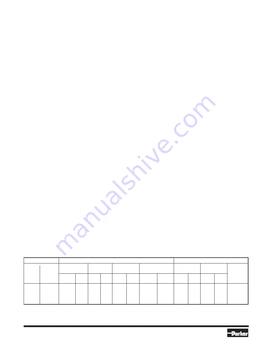
FLANGE TABLE
À
FPT FLANGES
WELDING FLANGES
Ã
O.D.S. FLANGES
Fit Pipe
Socket Weld
Weld Neck
Flange
Tubing
Fitting
Nominal
Size
Socket I.D.
Neck O.D.
Package No.
O.D.
I.D.
Pipe
Flange
Flange
Size
Package
Nominal
O.D.
Á
Socket
Weld
Â
Package
Inches
No.
Inches
mm
Inches
mm
Inches
min
Weld
Neck
Inches
mm
Inches
mm
No.
1/4
200000
1/4
13.25
.560
14.22
.540
13.72
200004
200008
3/8
200001
3/8
16.75
.695
17.65
.675
17.15
200005
200009
1/2
12.70
.502
12.75
200012
1/2
200002
1/2
21.25
.860
21.84
.840
21.34
200006
200010
5/8
15.87
.627
15.92
200013
3/4
200003
3/4
26.75
1.070
27.18
1.050
26.67
200007
200011
7/8
22.22
.877
22.27
200014
À
FPT – Internal NPT (USA Standard Taper Pipe Thread)
Á
Metric steel tubing used for refrigeration
Â
Metric copper tubing used for refrigeration
Ã
ODS Connections to fit copper tubing of given outside diameter
DEFINITIONS: O.D.S. – Outside Diameter Sweat; I.D. – Inside Diameter; O.D. – Outside Diameter
When ordering flanges, use the proper package number from Flange Table. A Flange Package consists of two flanges only.


