


Refrigerating Specialties Division
4
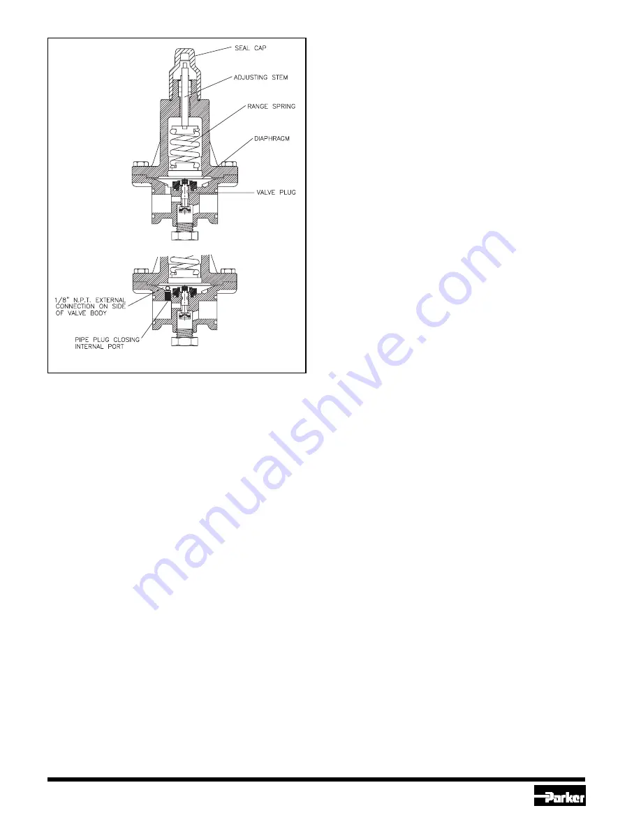
Principles of Operation A2BO, A2BOE
In the A2BO the outlet pressure is sensed under the diaphragm. As the
outlet pressure decreases below the set point, the range spring pushes
the diaphragm against the valve plug, moving the plug off the seat and
allowing flow through the regulator (Fig. 3). As the outlet pressure increases
it moves the diaphragm against the force of the range spring and allows
the valve plug to move towards its seat, thus reducing the flow through
the valve. When the outlet pressure exceeds the regulator set point, the
regulator is closed.
The A2BOE externally equalized pressure regulator operates like the A2BO
except the sensing pressure under the diaphragm is from a point
downstream of the valve (Fig. 4).
Adjustment A2BO, A2BOE
An accurate pressure gauge should be installed at the outlet of the regulator
(or at the pressure sensing point for A2BOE). In case of a compensated
pressure regulator, pressure gauges should be installed at the outlet of
the regulator and also at the compensating pressure to the bonnet.
Carefully remove the seal cap and turn the adjusting stem in (clockwise)
to raise the set point, tending to open the seat; or out (counterclockwise)
to lower the set point, tending to close the seat. Table 2 shows the set
point pressure ranges for the regulators. Do not attempt to exceed the
rated maximum pressure setting adjustment because this could damage
the regulator or make it inoperative. Severe over adjusting could also apply
enough force to damage the diaphragm, or put the spring in solid position.
So, if the maximum tightening adjustment has been reached, stop and
back out the adjusting stem (counterclockwise) at least one half turn so
the range spring can move.
After adjusting the regulator, it is advisable to observe the maintained
pressure while the system is operating normally, and to make any minor
adjustments desired at that time. Replace the seal cap after the desired
set point is reached.
TABLE 2. A2BO OUTLET PRESSURE SETTING RANGES
SET POINT RANGES
APPROX. CHANGE PER TURN
OF ADJUSTING SCREW
V: 500 mm hg to 8 bar
(20 in. hg to 120 psig)
1.8 bar (25 psi)
D: 5 to 19 bar (75 to 280 psig)
3.6 bar (53 psi)
Installation All A2 Regulators
Do not remove the protective coverings from the inlet and outlet of the
regulator until the regulator is ready to be installed. Protect the inside of
the regulator from moisture, dirt and chips before and during Installation.
When welded or brazed flange connections are used, all slag, scale, and
loose particles should be removed from the flange interior before the
regulator is installed between the flanges.
Tighten flange bolts and nuts evenly to provide proper seating of the flange
gasket and to avoid damage to gasket or flanges. A close coupled
companion strainer is available for installation at the inlet of the regulator
to help to protect it from any foreign material in the system.
The regulator must be installed with the arrow on the valve body pointing
in the direction of the flow for the regulator to function properly. Backwards
flow through the regulator is uncontrolled and will vary with the valve model,
its setting and the reverse pressure drop encountered. The regulator should
be installed in a location where it is easily accessible for adjustment and
maintenance. The location should be such that the regulator can not be
easily damaged by material handling equipment. When it is necessary to
insulate the regulator (and companion strainer), the insulation should be
installed to provide access to the regulator (and companion strainer) for
adjustment and maintenance. Proper indicating pressure gauges should
be installed to be easily visible to the operator adjusting the regulator.
Warranty
All Refrigerating Specialties Products are warranted against defect in
workmanship and materials for a period of one year from date of shipment
from factory. This warranty is in force only when products are properly
installed, maintained and operated in use and service as specifically stated
in Refrigerating Specialties Catalogs or Bulletins for normal refrigeration
applications, unless otherwise approved in writing by Refrigerating
Specialties Division. Defective products, or parts thereof, returned to the
factory with transportation charges prepaid and found to be defective by
factory inspection will be replaced or repaired at Refrigerating Specialties’
option, free of charge, F.O.B. factory. Warranty does not cover products
which have been altered or repaired in the field; damaged in transit, or
have suffered accidents, misuse, or abuse. Products disabled by dirt, or
other foreign substances will not be considered defective.
THE EXPRESS WARRANTY SET FORTH ABOVE CONSTITUTES THE
ONLY WARRANTY APPLICABLE TO REFRIGERATING SPECIALTIES
PRODUCTS, AND IS IN LIEU OF ALL OTHER WARRANTIES,
EXPRESSED OR IMPLIED, WRITTEN OR ORAL, INCLUDING ANY
WARRANTY OR MERCHANTABILITY, OR FITNESS FOR A PARTICULAR
PURPOSE. No employee, agent, dealer or other person is authorized to
give any warranties on behalf of Refrigerating Specialties, nor to assume,
for Refrigerating Specialties, any other liability in connection with any of
its products.
Safe Operation
(see also Bulletin RSBCV)
People doing any work on a refrigeration system must be qualified and
completely familiar with the system and the Refrigerating Specialties
Division valves involved, or all other precautions will be meaningless. This
includes reading and understanding pertinent Refrigerating Specialties
Division product Bulletins, and Safety Bulletin RSBCV prior to installation
or servicing work.
Where cold refrigerant liquid lines are used, it is necessary that certain
precautions be taken to avoid damage which could result from liquid
expansion. Temperature increase in a piping section full of solid liquid will
cause high pressure due to the expanding liquid which can possibly rupture
a gasket, pipe or valve. All hand valves isolating such sections should be
marked, warning against accidental closing, and must not be closed until
the liquid is removed. Check valves must never be installed upstream of
solenoid valves, or regulators with electric shutoff, nor should hand valves
upstream of solenoid valves or downstream of check valves be closed
until the liquid has been removed. It is advisable to properly install relief
devices in any section where liquid expansion could take place.
Avoid all piping or control arrangements which might produce thermal
or pressure shock.
For the protection of people and products, all refrigerant must be
removed from the section to be worked on before a valve, strainer, or
other device is opened or removed.
Flanges with ODS connections are not suitable for ammonia service.
Parker Hannifin Corporation • Refrigerating Specialties Division
2445 South 25th Avenue • Broadview, IL 60155-3891
Telephone (708) 681-6300 • Fax (708) 681-6306
Fig. 3
A2BO
Fig. 4
A2BOE


