Parker 8902/RE Technical Manual Download Page 7

3


8902/RE Resolver Speed Feedback Option 


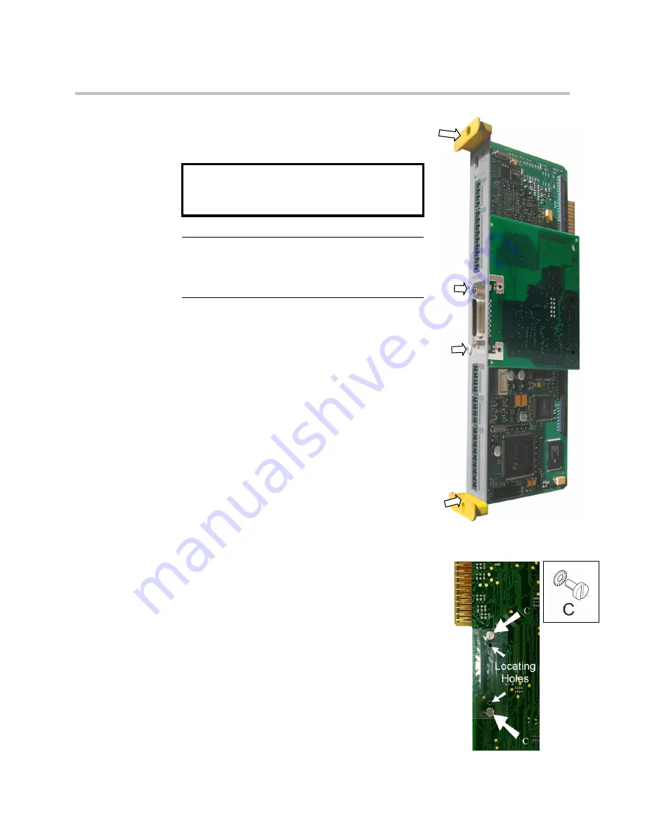
Figure 3  Rear of 

Control Board 

Installation 

Fitting the Option 

If the Option is not factory-fitted, follow the procedure 
given below. 

WARNING!


Disconnect all sources of power before 

attempting installation.  

Caution 

This Option contains ESD (Electrostatic Discharge) 

sensitive parts. Observe static control precautions 

when handling, installing and servicing this Option. 

1.


Undo the two screws securing Option A and Option B 
to the front of the drive. If Options are not fitted, 
completely remove the blank covers for the Option A 
and Option B slots. 

2.


Undo the screws (A) located in the top and bottom 
handles of the control board. Gently pull on the 
handles to withdraw the board from the drive, 
supporting any attached option boards. Note that the 
boards are sliding in top and bottom slots. 

3.


Remove any other Options that are fitted to the control 
board. 

4.


Offer up the Resolver Option through the "OPTION F" 
cut-out as shown opposite. 

5.


Fit the two locating pegs of the large connector on the 
rear edge of the option board into the locating holes on 
the control board, as shown below. 

6.


Fit the two screws and crinkle washers (C) at the rear edge of the Option. 
DO NOT OVERTIGHTEN. 
Tightening torque : 0.2Nm (28 oz-in). 

7.


Secure with the two screws (B) to the front of the control 
board.  

The front panel screws (B) are self-tapping and can be 
quite hard to turn.  This turning torque must not be 
transferred through the option board to the control board 
connector.  To avoid this hold the option board with one 
hand, while tightening the front panel screws with the 
other.  DO NOT hold the control board while tightening 
these screws. 

8.


Refit any other Options that were removed from the control 
board. 

9.


Replace the control board (with attached Options) into the 
drive.  

10.


Tighten the Option A and Option B screws; or importantly, 
fit the blank covers and secure with the screws. 

Summary of Contents for 8902/RE

Page 1: ...rker SSD Drives a division of Parker Hannifin Ltd Although every effort has been taken to ensure the accuracy of this document it may be necessary without notice to make amendments or correct omission...

Page 2: ...nt Application Area The equipment described is intended for industrial motor speed control utilising AC induction or AC synchronous machines Personnel Installation operation and maintenance of the equ...

Page 3: ...In particular Stored energy might not discharge to safe levels as quickly as suggested and can still be present even though the drive appears to be switched off The motor s direction of rotation might...

Page 4: ...and 8902 RR 1 Specifications Resolver Interface 8902 RE and 8902 RR 2 Specifications Emulated Encoder 8902 RR only 2 Recommended Spare Parts 2 Installation 3 Fitting the Option 3 Wiring the System 4...

Page 5: ...ntains a carrier output signal to power the Resolver 8902 RR contains three differential outputs emulating a pulse encoder Part Number The part number for the Resolver Speed Feedback Option is 8902 RE...

Page 6: ...s Resolution Equivalent to 16 bits per electrical revolution of resolver Inputs Differential inputs Zin 2 k Maximum input voltage 12Vpeak Isolation None Specifications Emulated Encoder 8902 RR only Si...

Page 7: ...er Options that are fitted to the control board 4 Offer up the Resolver Option through the OPTION F cut out as shown opposite 5 Fit the two locating pegs of the large connector on the rear edge of the...

Page 8: ...a screen over each individual pair It may be possible to use a cable with just a screen over each individual pair The signal pairs should have characteristic impedance of 120 To ensure compliance with...

Page 9: ...arrier input reference voltage 9 Sin input 10 11 Cos input 12 Index Z output 13 Quadrature A output 14 Quadrature B output 15 carrier input reference voltage not connected not connected not connected...

Page 10: ...Rotor COSINE input Vcos V S1 S3 V R1 R2 x TR x cos SINE input Vsin V S2 S4 V R1 R2 x TR x sin With Vin V R1 R2 carrier signal reference voltage TR transformation ratio position Approved Resolvers Par...

Page 11: ...nd Z These emulate a 1024 line encoder rotating at the same speed and direction as the resolver Clockwise rotation of the encoder shaft normally causes channel A to lead channel B but this could rever...

Page 12: ...SETUP MOTOR CONTROL RESOLVER This block allows Speed Feedback to be measured using a resolver Note Only parameters relevant to the Resolver are described below Parameter Descriptions NAME Range Resolv...

Page 13: ...the init state is completed and the speed and position information are normally available FALSE the initialisation phase is on going Position and speed information are not available The initialisation...

Page 14: ...when the motor runs in a clockwise direction looking to the front shaft of the motor the 3 successive phases are M1 M2 and M3 as shown below Motor phasing 0 90 180 270 360 electrical position M1 phas...

Page 15: ...Feedback Option ISS MODIFICATION ECN No DATE DRAWN CHK D 1 Add support for 8902 RR 17852 27 08 09 AFL FIRST USED ON MODIFICATION RECORD 8902 RE and 8902 RR Resolver Speed Feedback Options DRAWING NUMB...

Reviews: