Parker Hydraulics PGM 300 Series Service Manual Download Page 8

PGP/PGM 300 Series

Service Manual HY09-SM300/US

8

Parker Hannifin Corporation
Gear Pump Division
Youngstown, OH

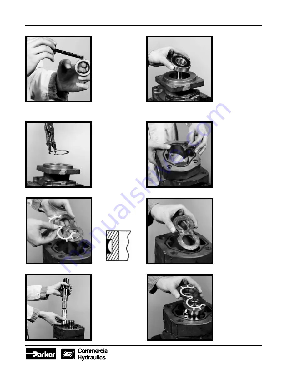
9) Before inserting a new lip
seal in the shaft end cover,
coat the outer edge of the
lip seal and its recess with
Permatex Aviation
Form-A-Gasket™ No. 3
non-hardening sealant or
equivalent. With the metal
side of the lip seal up, press
it into the mounting flange
side of the shaft end cover
with an arbor press and bar
(see Tool List  on  page 4).
Be careful not to damage
the lip of the seal. Press in
until flush with the recess.
Wipe off excess sealant.

10) If the unit is equipped
with an outboard bearing,
guide the bearing into its
recess in the shaft end
cover. This is a light
press fit. It may be
necessary to lightly tap
the bearing into the
bore.

11) Install the snap ring in
the groove to retain the
outboard bearing.

12) Grease the new gasket
seals and insert them into
the grooves in both sides of
all gear housings. Position
the first gear housing over
the shaft end cover and
dowels. Tap it with a soft
hammer until it rests tightly
against the shaft end cover.
Be careful not to pinch the
gasket seal. Also be sure
that the large rounded core
is on the inlet side.

16) Slip the thrust plate
with the seal over the gear
journals and into the
housing bore. The flat side
of the seal should face up
with the relief groove
facing the outlet side. (For
single pump assemblies
go directly to Step #21).

15) Slide the driven gear
through the housing and into
the bushing in the shaft end
cover. Coat the steel sleeve
tool with grease. Place the
lightly-greased drive shaft
inside the sleeve and slide
both through the shaft end
cover with a twisting motion,
until the integral gear rests
against the thrust plate.
Avoid damaging the double
lip seal. Remove the steel
sleeve. Squirt clean oil over
the gears.

14) Gently slip the thrust
plate through the gear
housing and into place on
the shaft end cover. The
channel seal from Step
#13 should face the shaft
end cover. The relief
groove in the plate should
face the outlet side of the
pump.

13) Assemble the channel
seals into the grooves in
the thrust plates with the
flat side of the seal facing
away from the thrust plate
as shown below.

Flat Side
of Seal

Thrust
Plate

Summary of Contents for PGM 300 Series

Page 1: ...Service Manual PGP PGM315 330 350 365 Service Manual HY09 SM300 US Effective April 15 2002 Supersedes July 1 1998 PGP PGM 300 Series ...

Page 2: ...ormance safety and warning requirements of the application are met The products described herein including without limitation product features specifications designs availability and pricing are subject to change by Parker Hannifin Corporation and its subsidiaries at any time without notice Offer of Sale The items described in this document are hereby offered for sale by Parker Hannifin Corporatio...

Page 3: ...VOID DAMAGING MACHINED SURFACES A pump must be driven in the direction of rotation for which it was built otherwise pressure will blow the shaft seal Check the exploded view and notes at right for proper direction of rotation Parker s Replacement Parts Parker s replacement parts are of original equipment standards For assured quality of material and work manship and for compatibility in assembly U...

Page 4: ... see sketch Special Steel Sleeve The special steel sleeve is used to insert the drive shaft through the lip seal without damage and can be made from bar stock For the PGP PGM315 use a 1 dia x 3 1 8 bar for the PGP PGM330 use a 1 1 8 or 1 1 4 dia x 4 5 8 bar for the PGP PGM350 use a 1 3 8 dia x 4 5 8 bar for the PGP PGM365 use a 1 1 2 dia x 4 5 8 bar The drawing and chart give details for making th...

Page 5: ...G ASSEMBLY OR DISASSEMBLY Match mark all sections Be sure to align these marks when reassembling 4 Remove the thrust plate Examine and replace if necessary See wear guide page 10 5 Carefully remove the drive and driven gears Avoid tapping the gear teeth together or against other hardened surfaces Keep these gears together because they are a matched set Examine and replace if necessary See page 10 ...

Page 6: ...t section gear housing Be careful not to damage machined surfaces Examine and replace if necessary see page10 13 Grip the shaft end cover in a vise with the mounting face down Remove double lip seal by inserting the special seal removal tool see Tool List into the notch between the double lip seal and the shaft end cover Tap the seal out and discard Remove and discard all rubber and polymer seals ...

Page 7: ...rrier should be assembled in the drive bores with the groove to the top of unit 12 o clock Assemble the bushings in the driven bores with the groove to the bottom of the unit 6 o clock The PGP PGM315 does not have grooved bushings therefore the bushing seams should be placed at the 12 and 6 o clock positions 8 See that dowel pins are in place in any new castings Examine all of the dowels Before in...

Page 8: ...ith a soft hammer until it rests tightly against the shaft end cover Be careful not to pinch the gasket seal Also be sure that the large rounded core is on the inlet side 16 Slip the thrust plate with the seal over the gear journals and into the housing bore The flat side of the seal should face up with the relief groove facing the outlet side For single pump assemblies go directly to Step 21 15 S...

Page 9: ...rs are in contact with the thrust plate face Place the port end cover plate in the housing per Step 16 For multiple assemblies only 20 Check the plug or plugs in the port end cover to be sure that they are tight Follow the procedure outlined in Step 4 for new plugs For multiple assemblies only 22 Thread the fasteners into the shaft end cover and tighten alternately or cross corner Rotate the drive...

Page 10: ...nation Wear or damage to splines keys or keyways necessitates replacement Thrust Plates The thrust plates seal the gear section at the sides of the gears Wear here will allow internal slippage that is oil will bypass within the pump A maximum of 002 wear is allowable Replace thrust plates if they are scored eroded or pitted Check center of thrust plates where the gears mesh Erosion here indicates ...

Page 11: ...al Recommendations A good quality hydraulic oil conforming to the characteristics listed above is essential to the satisfactory performance and long life of any hydraulic system The oil should be changed on regular schedules in accordance with the manufacturer s recommendations and the system periodically flushed The oil temperature in the reservoir must not exceed 200 F 93 3 C with a maximum temp...

Page 12: ...ve until the spring tension on the adjusting screw is relieved This will avoid the possibility of immediate damage to the replacement unit in the event that the relief valve setting had been increased beyond the recommended operating pressure prior to removing the old unit Before connecting any lines to the pump fill all ports with clean oil to provide initial lubrication This is particularly impo...

Page 13: ... immediately and locate the problem source Gradually increase pressure on pump in 500 psi increments until the desired test pressure has been reached This should take about five minutes Delivery should run close to rated catalog performance figures which are averaged from testing several pumps A 5 lower reading may be used as a rated minimum if new or relatively new parts have been used When rebui...

Page 14: ...all include without limitation accidents actsofGod strikesorlabordisputes acts laws rules or regulations of any government or government agency fires floods delays or failures in delivery of carriers or suppliers shortages of materials and any other cause beyond Seller s control 12 Entire Agreement Governing Law The terms and conditions set forth herein together with any amendments modifications a...

Page 15: ...technical support and global availability The Instrumentation Group is a global leader in the design manufacture and distribution of high quality critical flow components for worldwide processinstrumentation ultra high purity medical and analytical applications Parker s Charter To be a leading worldwide manufacturer of components and systems for the builders and users of durable goods More specifi...

Page 16: ...Parker Hannifin Corporation Gear Pump Division 1775 Logan Avenue Youngstown OH 44501 USA Tel 330 746 8011 Fax 330 746 1148 www parker com Service Manual HY09 SM300 US 04 02T M 2 5M ...

Reviews: