background image

Service Manual - PHP 1000 Pump                                                 


2008.04    V1.0


2


Service Instruction: 

Instruction for all general service repairs


WARNING 

Disconnect power cord from the 

mains plug, prior to any repair 


Attention: 


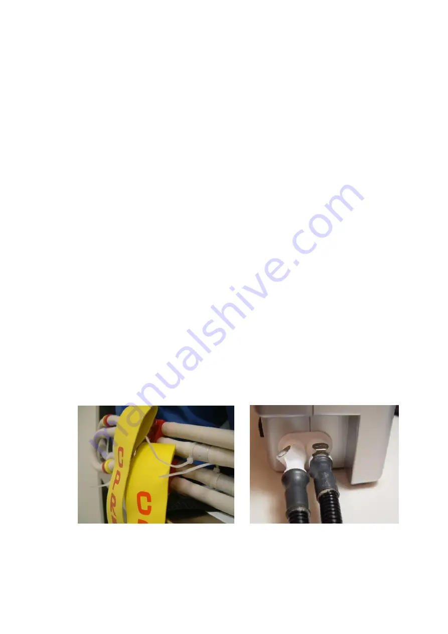
Before commencing the repair please follow instructions indicated 
from below. 


Such as CPR isn’t snapped securely, See Fig A 


Quick connectors are not connected securely to the control 

unit, See Fig B 


For all the required replacement parts, please contact 
your agent for part number. Once the BOM   

(Bill of Material) is obtained, proceed to the parts order 

and repair as follows. 


Fig A 


Fig B 

Summary of Contents for PHP1000

Page 1: ...pected member of the British Healthcare Trade Association and has BS EN ISO9001and EN46002 accreditation which is the specific quality standard for Medical devices All products are CE marked in accord...

Page 2: ...P CASE EXPLODED VIEW DIAGRAM 11 2 1 5 TOP CASE ASSEMBLY BOM 11 2 1 6 BASE CASE EXPLODED VIEW DIAGRAM 12 2 1 7 BASE CASE ASSEMBLY BOM 12 3 SERVICE CHECKLIST 13 3 1 SERVICE REPAIR SOP 14 3 1 1 T1 CHECK...

Page 3: ...8 04 V1 0 4 Side View 1 Air outlet CPC Connector Panel View Comfort Seat cushion Service LED Alarm mute Panel View Comfort Therapy Panel lock Power 1 Product View illustration 1 1 Front View 1 2 Panel...

Page 4: ...vice Manual PHP 1000 Pump 2008 04 V1 0 5 Rear View Bed Hooks 2 Bed Hooks cover 2 Fuse Box 2 Casing screws 6 Filter cover 1 Foam bumper 1 Side View 2 Power switch Power cord 1 4 Side view 2 1 5 Rear vi...

Page 5: ...tion Before commencing the repair please follow instructions indicated from below Such as CPR isn t snapped securely See Fig A Quick connectors are not connected securely to the control unit See Fig B...

Page 6: ...tch 4 Timing motor and control assembly 5 Fuse 2 6 Compressor assembly 7 Power cord socket 8 Connector assembly 1 Pressure sensor 3 PCB Wiring connection site_ 1 5 Timing motor micro switch socket 4 T...

Page 7: ...08 04 V1 0 8 1 Micro switch securing screws_x2 2 Timing Motor screws_x2 3 Buzzer securing screws_x2 4 Main PCB securing screws_x5 5 Grounding nut 1 Front panel PCB securing screws_x5 2 PCB Wiring conn...

Page 8: ...Service Manual PHP 1000 Pump 2008 04 V1 0 9 2 1 2 PUMP Exploded View Diagram Fig 2 1...

Page 9: ...013 0000 Screws PCS 9 12 F647A01 0000 Control PCB PCS 1 13 F644E01 0000 Timing motor assembly PCS 1 14 885012 0000 Screws PCS 2 15 F016A01 0000 Air outlet assembly PCS 1 16 F425A04 0000 Silicone tubin...

Page 10: ...BOM NO Item Description UOM Quantity 1 F641201 C080 Base case PCS 1 2 F372A01 0000 Hanger assembly PCS 2 3 371708 0000 Hanger cover PCS 2 4 955002 0000 Screws PCS 8 5 611702 0000 Filter cover PCS 1 6...

Page 11: ...BOM NO Item Description UOM Quantity 1 F641201 C080 Base case PCS 1 2 F372A01 0000 Hanger assembly PCS 2 3 371708 0000 Hanger cover PCS 2 4 955002 0000 Screws PCS 8 5 611702 0000 Filter cover PCS 1 6...

Page 12: ...04 V1 0 13 3 Service checklist General symptom encountered SOP Check pressure range T1 Pressure calibration T2 No Power T3 Lead wires disconnected T4 Pump is not functioning T5 Panel PCB LED light mal...

Page 13: ...om pressure meter to the control unit cannot fit securely please find appropriate connectors or ask your contact agent for assistance Once the connection is air tight observe the pressure to reach req...

Page 14: ...t be activated whether in high or low pressure at any time during testing 9 Follow the checklist below if an incorrect pressure is detected 10 Air leak detected from timing motor See timing motor and...

Page 15: ...and 14th step of T1 follow the steps below to calibrate the pressure STEP 1 Switch on the power The normal power supply light will be illuminated STEP 2 Press the comfort left right selection button a...

Page 16: ...hts should not be lit The compressor will not function because the timing motor is in the repositioning process STEP 5 Wait for the timing motor repositioning process to finish the low pressure LED li...

Page 17: ...mute button the low pressure LED will turn off The LED lights of Comfort 1 and Comfort 2 will light up and flash and the compressor will stop working It means the pulling air tubing calibration was fi...

Page 18: ...the LED lights of Comfort 1 and Comfort 2 will turn off After that the LED lights of Comfort 9 and Comfort 10 will light up and flash and the compressor will stop working It means the low pressure ca...

Page 19: ...bration For PHP 1000 pressure calibration procedure SOP STEP 11 Press the Alarm mute button the LED lights of Comfort 9 and Comfort 10 will turn off The LED light of On Off will flash 5 times and then...

Page 20: ...isconnected by the power surge or incorrect voltage input 3 Replace the new fuse and insert back to the box Fasten by using in line screwdriver turning clockwise to fasten the fuse box See Fig_2 4 Eve...

Page 21: ...wires disconnected T4 Connecting lead wires securely SOP 1 Wire lead connectors are equipped with safety hooks press down prior to remove wire leads 2 During assembly ensure the wire led connectors a...

Page 22: ...unctioning if not perform step 7 and 8 to replace components 5 Use a screwdriver to loosen the 2 screws that fixed to the timing motor 6 Replace with new according to the part number listed from the B...

Page 23: ...th new front panel PCB SOP 1 Using screwdriver to loosen the 5 secure screws found from the front panel PCB 2 Replace with new according to section 2 2 2 and refer to BOM to ensure correct part is use...

Page 24: ...lied is correct 2 Make sure the lead wires whether is plugged in or loosen 3 Use an appropriate screwdriver to loosen 2 screws found from the Buzzer 4 Replace with new according to the part listed fro...

Page 25: ...ce Manual PHP 1000 Pump 2008 04 V1 0 26 4 Recommend tools NB Name Specification 01 Pressure meter 0 150mmHg 02 Flow meter 0 10LPM 03 Wire cutter pliers N A 04 Crimping pliers N A 05 Philips screwdrive...

Page 26: ...5 1 Replacing Feed Tubes 1 Unzip the mattress cover 2 Fold back cover 3 Pull off 2 feed tubes at base of mattress see FIG 7 4 Replace with new feed tubes remember 1 tube is longer 5 Fold back cover a...

Page 27: ...Disconnect feed connector on cell 5 Slide out cell 6 Removal as above but in reverse 5 2 Replacing Base Sheet 1 As above except all 16 Cells NOTE Always test after 5 3 Replacing the Foam Insert 1 Unzi...

Page 28: ...arts PHSP013A Threaded male connector PHSP013B Threaded female connector PHSP015 Side rail complete PHSP016 Cell each PHSP017 Base sheet PHSP018 Set of male female connectors PHSP019 Feed pipes includ...

Reviews: