


Figure 2 – Schematic
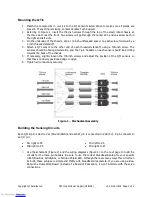
Use the Figure 4 to connect the servo extension cables to the male-male headers that are plugged into
the breadboard. The other end of each cable is plugged into a QTI. Be careful when you make these
connections, and pay close attention to the wire colors listed in the figure. Notice that the far left and mid
left cables have white wires that plug onto header pins in the same breadboard row. The same applies to
the mid right and far right QTI cables. Instead of common white wires, the mid left and mid right QTI
cables share a pair of black wires.
Boe-Bot
ActivityBot
Shield-Bot
Figure 3 – Wiring Diagrams
Copyright © Parallax Inc.
QTI LIne Follower AppKit (#28108)
v3.0 2/25/2015 Page 3 of 4
Downloaded from
Downloaded from
Downloaded from


