background image

(800) 471-8769 


14

Copyright 2021 © Paragon Tank Truck Equipment

Complete prior to blower operation


Truck #_________________________ 

Transmission#___________________ 

P.T.O.#_________________________ 

P.T.O. Ratio _____________________ 

Read and understand Installation Manual. 

The following have been verified before installing the PTO: 

PTO model # matches packaged model #. 

PTO mounting flange is correct for desired P657 mounting location. 

PTO ratio has been verified. 

PTO torque capabilities are acceptable for blower operation. 

PTO rotation is correct for desired P657 orientation. 

PTO is mounted per manufacturer’s recommendation. 

Transmission has been filled to the proper oil level as required by the manufacturer. 

The Blower can be rotated by hand without lobes touching or clashing. 

Drive shaft is installed correctly. 

Provided drive shaft flange set screws have been installed with “Loctite® 243” or equivalent. 

Air Inlet is installed as far away from heat sources as possible. 

All bolt torques have been verified. 

All supplied warning labels have been installed. 

The correct Relief Valve has been installed properly. 

Melt Plug is installed on the discharge side of the blower. 

Sight glasses and magnetic drain plug can be seen to identify oil level in P657 oil tanks after 

installation. 

Breathers are installed in the proper location. 

P657 front and rear oil tanks are filled to the proper levels (1/2 to 7/8 full).

Blower model #  P657 Blower                

Blower serial # __________________ 

Date__________________________ 

Inspected by____________________ 

Safety Checklist 

Summary of Contents for P657

Page 1: ...Installation and Operation Manual Truck Blower P657 Operators Manual Version 05 12 2021 Supersedes 07 20 2020...

Page 2: ...ion install a guard Use provided drive shaft flange set screws and apply Loctite 243 or equivalent Install a support strap when servicing a drive shaft to prevent personal injury A serious or fatal in...

Page 3: ...800 471 8769 2 Copyright 2021 Paragon Tank Truck Equipment Safety Notice...

Page 4: ...Mounting 5 Power Take Off 5 Blower Orientation 5 Mounting Bracket Requirements 7 Drive Shaft Installation 7 Determine Blower Mounting Slope 7 Suction Equipment 9 Delivery Discharge Pipework 9 ECM TCM...

Page 5: ...inHg 17 inHg CFM HP CFM HP CFM HP CFM HP CFM HP CFM HP CFM HP 1000 246 19 247 10 222 12 1100 282 21 265 28 283 11 258 13 1200 318 23 301 31 293 34 319 12 294 14 1300 354 25 337 33 329 37 321 41 355 1...

Page 6: ...haft angles to a minimum Ensure sight glasses melt plugs magnetic plugs and breathers are in the correct positions prior to mounting Note Melt plugs are left hand threads One plug must be on the disch...

Page 7: ...ounter Clockwise Sight Glass Breather Magnetic Drain Plug Out In Horizontal Airflow HA Vertical Airflow VA 1 2 3 4 5 6 7 8 In Sight Glass Breather Magnetic Drain Plug Out Sight Glass Breather Magnetic...

Page 8: ...erations for the required rpm Equipment slopes are correct to minimize torsional vibrations Confirm the drive shaft working angles are within industry specifications for safe operation See Fig 4 A min...

Page 9: ...1 5 8 w 3 8 key Paragon Part Number 560 044 Included with Paragon Mounting Kits 1350 Drive Flange 1 5 8 w 3 8 key Paragon Part Number 560 039 Drive Shaft to be field supplied not provided by Paragon...

Page 10: ...Ensure a Vacuum Relief Valve is used if any equipment will be used for vacuum duty of any kind Ensure Vacuum Relief Valve is sized for the correct CFM Ensure Vacuum Relief Valve rating does not excee...

Page 11: ...eration parameters Note For more available options regarding ECM TCM programming please contact your local chassis dealer Engine is off and keys are not in the ignition Ensure all connections are supp...

Page 12: ...er as per trailer manufacturer s recommendation While discharging visually check blower for vibration mechanical noise or excessive heat If blower relief valve or melt plug is activated reduce the lin...

Page 13: ...oz 0 9 qt 48 oz 1 5 qt Max Oil Fill Level Max Oil Fill Level Fig 6 Lubrication Instructions Use Paragon Lobe Blower Oil part number 409 007 Caution Mixing or incorrect oil can result in gear and bear...

Page 14: ...ogram change oil in both tanks every 500 hours Note Correct Oil Level is 1 2 to 7 8 full on the sight glass See Fig 6 Page 12 Air bubble must be visible at the top of sight glass Daily 1 Check and mai...

Page 15: ...vel as required by the manufacturer The Blower can be rotated by hand without lobes touching or clashing Drive shaft is installed correctly Provided drive shaft flange set screws have been installed w...

Page 16: ...800 471 8769 15 Copyright 2021 Paragon Tank Truck Equipment...

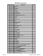
Page 17: ...Retainer Bushing 2 22 529 003 Timing Gear Set 1 23 124 027 Capscrew 10 24 510 006 Double Row Bearing 2 25 523 036 Blower NDE Cover 1 26 228 030 Capscrew 8 27 571 022 Drive Gear Spacer 1 28 582 022 Spi...

Page 18: ...t P657 CDL9 CDL12 Not Shown 1 J 526 000 Gasket 1 O 184 004 SS hex body for Filter Band Clamp 1 Item P N Description Qty A 576 009 Cap Assembly PSI VAC 1 B 576 012 Rubber Flex Latch 2 C 576 010 Head As...

Page 19: ...57 1 16 509 034 Flange Suction Alum P657 1 17 224 023 Capscrew Socket Head 4 P N Description Qty 18 296 012 Flat Washer 4 19 291 002 Hose Clamp Worm 2 20 563 002 Muffler 4 TTMA X 4 FNPT Steel 1 21 533...

Page 20: ...4 od X 24 long 1 7 587 018 Hose Hump 4 1 8 526 036 Gasket Delivery Suction P657 1 9 509 032 Flange Suction Alum P657 HA 1 10 291 012 Hose Clamp 4 6 1 P N Description Qty 11 291 002 Hose Clamp 3 5 3 1...

Page 21: ...et Driver Side 1 8 508 114 Mounting Bracket Passenger Side 1 9 601 012 P657 Blower 1 10 560 044 Drive Flange 1 11 509 034 Suction Flange 1 12 224 023 Capscrew Socket Head 4 P N Description Qty 12 228...

Page 22: ...ve and its approval Seller shall either repair or replace its product part or work at the original Ex works point of shipment or refund an equitable portion of the purchase price The products and part...

Reviews: