background image

Form M014-15-00-00 version 3

© 2019 Paragon Pro Manufacturing Solutions All Rights Reserved.

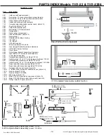
PARTS INDEX Models 1101-22 & 1101-2296

Base End Section Components

- 12 -

6-01

9-10

10-00

7-10 Complete Telescoping Ladder Section

7-01

7-02

8-45 Complete Beam Assembly

 (model 1101-22)

8-47 Complete Beam Assembly

(model 1101-2296)

8-06 8-05

8-46


(model 1101-22)

8-48

 (model 1101-2296)

8-03

8-49


(model 1101-22)

8-50

 (model 1101-2296

8-02


(model 1101-22)

8-32

 (model 1101-2296

8-04

8-18

8-17

8-39 8-38

8-16

8-26

8-37

8-13

8-08

8-40

8-41

PARTS LIST

Part Description

6-01

Latch pin with fasteners (each)

6-2A

End section “A” (crank side) without removable parts

6-2B

End section “B” (non-crank) without removable parts

7-01

Cable sheave with Axle and Pin

7-02

Ladder lock spring pin with fasteners

7-10

Complete telescoping ladder section (each) (total of 2)

8-02

Winch tube Model 1101-22

8-03

Latch Bolt assembly (pair)

8-04

Ball bearing (1/2” diameter hole)

8-05

Spring socket

8-06

Cable spring (compression)

8-08

Fiber washer (each) (total of 2)

8-13

Nylon washer

8-16

Serrated end bushing w/ spring

8-17

1/2” washer

8-18

1/2” cap nut

8-26

30 Tooth Sprocket

8-32

Winch tube Model 1101-2296 

8-36

Inner Hanger Bracket Assembly w/ fasteners

8-37

38 Pin #35 Chain w/ fastener

8-38

Chain Guard

8-39

Outer Hanger Bracket Assembly w/ fasteners

8-40

Input Shaft w/ 12 tooth sprocket & fasteners

8-41

Crank Handle Assembly

8-45

Complete beam assembly for Model 1101-22

8-46

Cable Asmbly. 1/8” x 29’ 11” with fasteners for Model 1101-22

8-47

Complete beam assembly for Model 1101-2296

8-48

Cable Asmbly. 1/8” x 31’ 8” with fasteners for Model 1101-2296

8-49

Beam body with sleeve bearings Model 1101-22

8-50

Beam body with sleeve bearings Model 1101-2296

9-10

Outrigger with stop bolt (each) (total of 4)

10-00 

5” Caster, brake mechanism & fasteners (ea.) (total of 4)

12-10 

Deck for Model 1101-22

12-11 

Deck for Model 1101-2296

13-00 

Brace (each) (total of 6)

14-14 

Model 1101-22 Guard rail w/ chain (each) (total of 4)

14-15 

Model 1101-2296 Guard rail w/ chain (each) (total of 4)

14-09 

Safety Chain 23.5”(each) (total of 4)

8-36

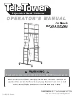
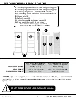
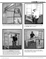
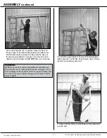
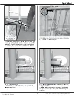
Summary of Contents for Tele-Tower 1101-22

Page 1: ...1 22 1101 2296 Model 1101 22 illustrated in this manual Before operating this equipment thoroughly read this set of instructions make sure you understand them and only then follow the step by step dir...

Page 2: ...t We take pride in providing the best for our customers Quality innovation and excellence are all qualities this company ensures No product is sent without being factory tested and inspected to ensure...

Page 3: ...Care Maintenance Page 4 Assembly Pages 5 7 Operation Pages 8 9 ASME Standards for Wire Rope Page 10 Parts Index Pages 11 12 Safety Information Page 13 CONTENTS This manual covers TELE TOWER Adjustable...

Page 4: ...r or outside the guard rail system to access work Over extending can create a fall hazard DO NOT extend the length or width of the Tele Tower Adjustable Work Platform beyond the manufacturer s supplie...

Page 5: ...ladder lock pins are fully engaged and the cable is prop erly strung and taut under the sheaves the base outriggers are extended to maintain a height to base ratio in keeping with applicable federal s...

Page 6: ...from the top platform The lower platform is not de signed as a work area ALWAYS adjust the base outriggers to maintain a height to base ratio in accordance with federal state and local standards A Tel...

Page 7: ...arings and ensure proper function of caster brakes and locks Remove foreign substances from base outriggers for smooth operation Apply household paraffin to the base outriggers and to the vertical sur...

Page 8: ...the input shaft Secure in place with the pull pin 3B Rotate winch handle and release cable from storage on beam 2 Engage ladder lock pins and lock one caster on end Section B Allow casters on Section...

Page 9: ...ate the Tele Tower Adjustable Work Platform without these braces Doing so can result in damage to the structure which can lead to failure that can result in severe prop erty damage and or severe bodil...

Page 10: ...and the base of the telescoping ladders Jog base of end sections to fa cilitate brace pin alignment DO NOT hammer on braces WARNING NEVER use the Tele Tower Adjustable Work Platform at deck heights o...

Page 11: ...Tele Tower Adjustable Work Platform 2a TO ELEVATE DECK Retract and rotate the ladder lock spring pins to the disengaged position 2b Rotate winch handle counterclockwise until deck is 2 4 below the de...

Page 12: ...clockwise while the ladder lock pins are engaged Doing so will allow the cable to go slack which can cause the cable to wind unevenly on the winch tube This will cause the two telescoping ladders to m...

Page 13: ...ctual condition of the internal structure 00 General The use of cableways cranes derricks hoists hooks jacks and slings is subject to certain hazards that cannot be met by mechanical means but only by...

Page 14: ...Manufacturing Solutions All Rights Reserved PARTS INDEX Models 1101 22 1101 2296 11 14 09 6 2A 6 2B 14 14 Model 1101 22 14 15 Model 1101 2296 12 10 Model 1101 22 12 11 Model 1101 2296 8 45 Model 1101...

Page 15: ...05 Spring socket 8 06 Cable spring compression 8 08 Fiber washer each total of 2 8 13 Nylon washer 8 16 Serrated end bushing w spring 8 17 1 2 washer 8 18 1 2 cap nut 8 26 30 Tooth Sprocket 8 32 Winc...

Page 16: ...velopmental 67 56 1 Trace Methylene Chloride Dichloromethane Cancer 75 09 2 Trace Nickel Cancer 7440 02 0 Trace Propylene glycol monobutyl ether Cancer 5131 66 8 Trace Toluene Developmental 108 88 3 T...

Page 17: ......

Page 18: ......

Page 19: ......

Page 20: ...facturing Solutions All Rights Reserved Questions about assembly Can t find a part Need some other help Call us 1 800 448 0822 We ll get you set up Paragon Pro Manufacturing Solutions 7251 S 42nd St G...

Reviews: