


OPERATION INSTRUCTIONS
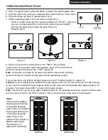
8. Push in and turn the control knob to the “HIGH”, then release
control knob. If you want a lower temperature, push in the control knob
and turn counterclockwise to the “LOW” (
Figure 5)
.
Note: If pilot fails to remain lit, all valves should be closed and a waiting
period of at least 5 minutes should pass before attempting to light.
If you experience any ignition problem please consult “Troubleshooting” on page 18.
Caution: Avoid inhaling fumes emitted from the heater’s first use. Smoke and odor from the burning
of oils used in manufacturing will appear. Both smoke and odor will dissipate after approximately 30
minutes. The heater should NOT produce thick black smoke.
Note: The burner may be noisy when initially turned on. To eliminate excessive noise from the burner,
turn the control knob to the PILOT position. Then, turn the knob to the level of heat desired.
Figure 3
Figure 4
Figure 5
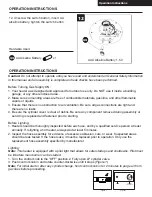
Igniter
Variable
control knob
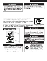
Normal
Abnormal
-Repeat step 6.
through the glass tube to light the pilot (
Figure 4)
.
-As you are depressing the control knob, place long stem lighter
-Push in control knob and turn counterclockwise to “PILOT” (
Figure 3)
.
If after repeating steps 4 to 6 unit does not light, then
7.
If the pilot does not stay lit, repeat steps 4 to 6.
6.
Once the pilot is lit, continue to depress the control knob for 30 seconds.
5.
Push the igniter button until pilot flame is visible throughthe glass tube.
4.
abnormal condition.
Contrarily it is
stable and bright.
position.The flame is
tube under Low
1/3 height of glass
the height of flame is
tube under Hi position.
2/3 height of glass
the height of flameis
In Normal condition,
Note:
14
OPERATION INSTRUCTIONS
Operation Instructions
Summary of Contents for OH-M744S
Page 18: ...5016039...