background image

 11

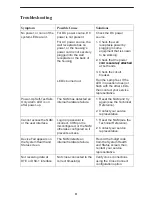
Troubleshooting

Symptom

Possible Cause

Solutions

No power, or none of the
system LEDs are lit.

For DC power source, DC
power is not present.

For AC power source, the
wall receptacle has no
power, or the housing’s
power cord is not securely
plugged into the wall
receptacle or the back of
the housing.

Check the DC power
source.

1. Check the wall

receptacle power by
plugging in some
equipment that is known
to be working.

2. Check that the power

cord is securely attached

t e ous g

LED is burned out.

cord is securely attached
at both ends.

3. Check the circuit

breaker.

Run the Lamp Test. If the
LED in question does not
flash with the other LEDs,
then contact your service
representative.

Power-Up Self-Test fails.
Only Alarm LED is on
after power-up.

The NAM has detected an
internal hardware failure.

1. Reset the NAM and try

again (see the Technical
Reference).

2. Contact your service

representative.

Cannot access the NAM
or the user interface.

Login or password is
incorrect, COM port is
misconfigured, or the NAM
otherwise configured so it
prevents access.

1. Reset the NAM (see the

Technical Reference).

2. Contact your service

representative.

Device Fail appears on
the System Health and
Status screen.

The NAM detects an
internal hardware failure.

Record the 8-digit code
from the System Health
and Status screen, then
contact your service
representative.

Not receiving data at
DTE or DSX-1 interface.

Not cross-connected to the
correct timeslot(s).

Verify cross connections
using the Cross Connect
configuration option.

Summary of Contents for Single T1 Network Access Module (NAM)...

Page 1: ...e Support Technical Manuals T1 Access Multiplexers Select the following document 9161 A2 GH30 Model 916x 926x T1 Access Mux Technical Reference To request a paper copy of a Paradyne document Within the U S A call 1 800 PARADYNE 1 800 727 2396 Outside the U S A call 1 727 530 8623 Before You Begin Make sure you have An operable T1 network connection An async VT100 compatible terminal emulator Housi...

Page 2: ...r nearest sales or service representative Available Options The following options are separately orderable RJ48C modular cable for network access 20 ft RJ48H T1 mass termination cable 5 ft for connecting seven T1 NAMs to an M66 block What Does a T1 NAM Do The T1 NAM acts as an interface between the T1 digital network and the customer premises equipment converting signals received from the DTE to b...

Page 3: ... DTE adapter cable for each port Port 1 and or Port 2 1 ft DTE with a V 11 X 21 interface connector DB15 to DB25 adapter cable for each port Port 1 and or Port 2 1 ft LAN Adapter COM Port to LAN Adapter cable 14 ft Modem 8 pin modular to DB25 connector Modem cable Recommended Order of Installation 1 First install the I O card 2 Connect all cables into the I O card 3 Install the NAM 4 Go to the app...

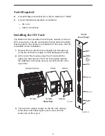
Page 4: ...e NAM that it supports Slot numbers are identical in this case Slot 01 to facilitate correct installation 1 Remove the I O card from the shipping box Handle only by the top and bottom edges to avoid damaging the card 2 At the rear of the housing align the I O card with the upper and lower tracks of the slot Push gently towards the midplane until it stops and you cannot push the card any further 97...

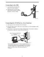
Page 5: ...he other end of the cable into the RJ48C modular jack Connecting to a DTE If the DTE cable type is V 35 RS449 or V 11 X 21 separately orderable 1 Connect the plug to the V 35 RS449 or V 11 X 21 end of the adapter cable as appropriate 2 Connect the EIA 530A end of the adapter cable to PORT 1 or PORT 2 If the DTE cable type is EIA 530A 1 Connect the EIA 530A end of the DTE cable to PORT 1 or PORT 2 ...

Page 6: ...atible terminal emulation connector 3 Press Return on the keyboard to display the Main Menu If you need to configure for other than a direct link see the Technical Reference Set the speed of the async VT100 compatible terminal so it matches the NAM s factory loaded data rate of 19 2 kbps character length set to 8 parity set to None and stop bits set to 1 The flow control should be set to None or H...

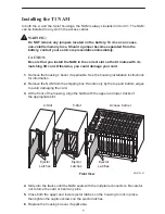
Page 7: ...emove the housing s bezel if applicable See the housing installation instructions for information 2 Remove the NAM from the shipping box Handle only by the top and bottom edges to avoid damaging the card 3 At the front of the housing align the NAM with the upper and lower tracks of the appropriate slot 2 Slot Ejector Latches 98 15750 01 Ejector Latches Front View 5 Slot Ejector Latches Access Carr...

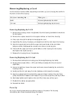
Page 8: ... Close both the upper and lower ejector latches on the housing to lock in place then tighten the captive screws 7 Replace the housing s bezel if applicable Removing Replacing the I O Card 1 Remove the NAM from the housing see Removing Replacing the NAM 2 Remove the network DSX 1 DTE and COM port cables from the I O card if applicable 3 Using a screwdriver loosen the upper and lower screws fastenin...

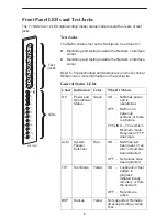
Page 9: ...bleshooting and Maintenance in the Technical Reference for more information on the test jacks General Status LEDs Label Indication Color What It Means OK Power and Operational Status Green ON NAM has power and is operational OFF NAM is in a power up self test or there is a failure CYCLING The unit is in Minimum mode Requires an FTP download ALM System Failure Self Test Red ON NAM has just been res...

Page 10: ...esent on the network DSX interface Current alarm conditions Loss of Signal LOS Loss of Frame LOF Excessive Error Rate EER Yellow Alarm Alarm Indication Signal AIS OFF No alarm condition is present on the network DSX interface Port 1 and Port 2 LEDs Label Indication Color What It Means 1 OK 2 OK Operational Status Green ON The interchange circuits for the port are in the correct state to transmit a...

Page 11: ...act your service representative Power Up Self Test fails Only Alarm LED is on after power up The NAM has detected an internal hardware failure 1 Reset the NAM and try again see the Technical Reference 2 Contact your service representative Cannot access the NAM or the user interface Login or password is incorrect COM port is misconfigured or the NAM otherwise configured so it prevents access 1 Rese...

Page 12: ...ce Physical Interface USA Physical Interface Canada Framing Format Coding Format Line Build Out LBO ANSI PRM Bit Stuffing Yellow Alarm Generation RJ48C CA81A using adapter cable D4 ESF AMI B8ZS 0 0 dB 7 5 dB 15 dB 22 5 dB Selectable FCC Part 68 AT T TR 62411 Selectable DSX 1 Interface Physical Interface Framing Format Coding Format DTE Line Equalization Send AIS DB15 socket D4 ESF AMI B8ZS 5 selec...

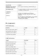
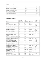
Page 13: ...ater Loopback DSX 1 Line Loopback DSX 1 Payload Loopback DSX 1 Repeater Loopback DTE Loopback Pin Assignments NET Port Interface Function Circuit Pin Receive ring from the network R1 1 Receive tip from the network T1 2 Transmit ring to the network R 4 Transmit tip to the network T 5 COM Port Interface Signal Direction Pin DCE Transmit Clock TXC Out 1 DCE Receive Data RXD Out 2 Signal Ground SG 3 D...

Page 14: ...ar to Send CTS CB 106 From DCE 5 A 13 B Data Set or DCE Ready DSR CC 107 From DCE 6 Signal Ground Common SG AB 102A 7 Received Line Signal Detector RLSD or LSD CF 109 From DCE 8 A 10 B Transmit Signal Element Timing TXC DTE Source DA 113 To DCE 11 B 24 A Transmitter Signal Element Timing TXC DCE Source DB 114 From DCE 12 B 15 A Receiver Signal Element Timing RXC DCE Source DD 115 From DCE 17 A 9 B...

Page 15: ...via fax or to speak with a company representative Within the U S A call 1 800 870 2221 Outside the U S A call 1 727 530 2340 Document Feedback We welcome your comments and suggestions about this document Please mail them to Technical Publications Paradyne Corporation 8545 126th Ave N Largo FL 33773 or send e mail to userdoc eng paradyne com Include the number and title of this document in your cor...

Reviews: