Initial Startup and Configuration
3-6
7986-A2-GB20-00
September 1998
Configuring the Unit Using the Internal Switches
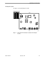
Use internal Switchpacks S1 and S2 to manually configure the unit. Use
Figure 3-1 to locate Switchpacks S1 and S2.
!
HANDLING PRECAUTIONS FOR
STATIC-SENSITIVE DEVICES
This product is designed to protect sensitive components from damage
due to electrostatic discharge (ESD) during normal operation. When
performing installation procedures, however, take proper static control
precautions to prevent damage to equipment. If you are not sure of the
proper static control precautions, contact your nearest sales or service
representative.
"
Procedure
To configure the unit using internal Switchpacks S1 and S2:
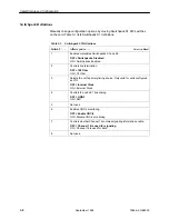
1. Power down the unit and remove the enclosure cover, exposing the circuit
board.
2. Locate Switchpack S1 using Figure 3-1.
3. Set Switch 1 on Switchpack S1 to ON to enable Switchpacks 1 and 2.
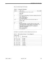
4. After you enable the switchpacks, you must set the switches to your desired
configuration. Refer to
Figure 3-1
and
Table 3-1
.
5. Replace and secure the cover.
6. Power up the board to reset and enable the new configuration.
496-15104
Summary of Contents for M/HDSL Standalone Termination Unit HOTWIRE...
Page 68: ...Testing 5 10 7986 A2 GB20 00 September 1998 This page intentionally left blank...
Page 80: ...Security 7 6 7986 A2 GB20 00 September 1998 This page intentionally left blank...
Page 106: ...Standards Compliance for SNMP Traps B 6 7986 A2 GB20 00 September 1998...
Page 114: ...Technical Specifications D 2 7986 A2 GB20 00 September 1998 This page intentionally left blank...


