background image

 8

8546-A2-GN10-20

October 1997

Connecting the DSL Cards to the Ethernet Hubs or Switches

"

Procedure

To connect the 8546 DSL cards to the Ethernet hubs or switches:

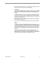
1. Plug the end of an 8-pin modular cable into the appropriate LAN/WAN SLOT

port of the chassis. For example, if you want to connect to the LAN/WAN port
of an 8546 DSL card, insert the 8-pin modular cable in LAN/WAN Slot #2.

2. Plug the other end of the cable into your Ethernet hub or switch connector.

Refer to 

Pin Assignments on page 9 for pin assignments.

— On a HotWire 8600 DSLAM chassis:

97-15375-01

LAN/WAN SLOT

2

A

IN

B

DC PWR

OUT

SERIAL

MCC

1

MANAGEMENT

3

A

AC

INPUT

AC

48VDC CLASS 2 OR

LIMITED PWR SOURCE

RTN

48V

A

A B

B

T5A

250A

LAN/WAN SLOT

2

4

6

B

..

.

3

.

1

2

POSITION

STACK

ALM

A

IN

B

DC FUSES

T4A, MIN. 48V

5

DC PWR

FAN

OUT

SERIAL

MCC

1

MANAGEMENT

3

LINE

1

2

3

SYSTEM

OK Alrm Test

TX RX Col

ETHERNET

MCC

8000

SYSTEM

OK Alrm Test

TX RX Col

1

2

3

4

ETHERNET

DSL

 POR

T

RADSL

8546

SYSTEM

OK Alrm Test

TX RX Col

1

2

3

4

ETHERNET

DSL

 POR

T

RADSL

8546

To Hub Connector

— On a HotWire 8800 DSLAM chassis:

MGT
SERIAL

MGT
10BT

ALARM

SLOTS   1 - 6

SLOTS   7-12

SLOTS 13-18

LINES

A

B

-48V (A)

-48V INPUT

-48V (B)

RET

 (A)

RET

 (B)

FR GND

2

4

6

8

10

12

14

16

18

19

1

3

5

7

9

11

13

15

17

LAN/WAN  SLOT

20

LAN/WAN  SLOT

MGT

SERIAL

MGT
10BT

ALARM

2

4

6

8

10

12

14

16

18

19

1

3

5

7

9

11

13

15

17

LAN/WAN  SLOT

20

LAN/WAN  SLOT

LAN/WAN SLOT

PORT 1

97-15385

Summary of Contents for HotWire 8546

Page 1: ...is connected to a HotWire 5446 Remote Termination Unit RTU it provides high speed Internet or Intranet access with dynamic IP addressing and enhanced security over traditional twisted pair telephone w...

Page 2: ...0 to 50 C 4 F 20 C to 158 F 70 C 5 to 85 noncondensing Withstands normal shipping and handling Criteria of technical specifications are subject to change without notice Planning the DSL Card Installa...

Page 3: ...small to medium size flat blade or Phillips screwdriver to install the 8546 DSL card When using a Install the DSL card into HotWire 8600 DSLAM base chassis Slot 2 or 3 Slot 1 of the HotWire 8600 DSLAM...

Page 4: ...ENT 3 LINE 1 2 3 97 15374 01 S Y S T E M O K A lr m T e s t T X R X C o l E T H E R N E T RADSL 8000 S Y S T E M O K A lr m T e s t T X R X C o l 1 2 3 4 E T H E R N E T D S L P O R T For a HotWire 88...

Page 5: ...to the Troubleshooting chapter of the appropriate HotWire DSLAM Installation Guide 5 Secure the DSL card by fastening the screws at each end of the faceplate NOTE The 8546 DSL cards may be replaced wi...

Page 6: ...nect the HotWire DSLAM chassis containing the 8546 DSL card to a POTS splitter shelf or MDF 1 Plug the Telco 50 pin cable into the appropriate LINE port on the front panel of the chassis On a HotWire...

Page 7: ...s through the tie mount to hold the Telco 50 pin connector in place If more than one Telco cable is being connected replace the existing cable tie with a single tie to span the two or three connectors...

Page 8: ...NPUT AC 48VDC CLASS 2 OR LIMITED PWR SOURCE RTN 48V A A B B T5A 250A LAN WAN SLOT 2 4 6 B 3 1 2 POSITION STACK ALM A IN B DC FUSES T4A MIN 48V 5 DC PWR FAN OUT SERIAL MCC 1 MANAGEMENT 3 LINE 1 2 3 S Y...

Page 9: ...tWire 8600 DSLAM LAN WAN Connector Pinouts The 8 pin modular interface for the LAN WAN 10BaseT connection on a HotWire 8600 DSLAM chassis has the following pin assignments Pin Number Use 1 TX Data 2 T...

Page 10: ...le lists the pin assignments for each of these interfaces NOTE When the 8600 chassis is the base chassis the MCC is installed in Slot 1 and the Tip and Ring wiring for Slot 1 is not active Also pins 1...

Page 11: ...4 4 29 Card 2 Port 1 Card 8 Port 1 Card 14 Port 1 5 30 Card 2 Port 2 Card 8 Port 2 Card 14 Port 2 6 31 Card 2 Port 3 Card 8 Port 3 Card 14 Port 3 7 32 Card 2 Port 4 Card 8 Port 4 Card 14 Port 4 8 33 C...

Page 12: ...Blinking Off A packet is being sent Inactive RX Green Blinking Off A packet is being received Inactive Coll Off Blinking Normal operation A collision has been detected DSL PORT 1 Green Off Amber Link...

Reviews: