


Configuration Options
4-15
9783-A2-GB20-00
July 2000
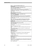
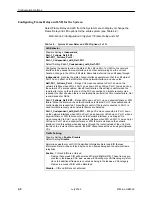
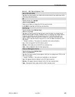
Table 4-6.
Data Port Physical Interface Options (2 of 2)
Monitor DTR
Possible Settings: Enable, Disable
Default Setting: Enable
Specifies whether the state of the DTE Ready (DTR) circuit on the user data port will be
used to determine when valid data communication is possible with the DTE. When the
DTR off condition is detected, an alarm is generated, LMI is declared down, and no
further transfer of frame relay data can occur on this interface.
Enable – Interchange circuit CD (ITU 108/1/2) – DTR is monitored to determine when
valid data is sent from the DTE.
Disable – DTR is not monitored. DTR is assumed to be asserted and data is being
transmitted, regardless of the state of the lead.
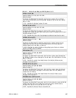
Port (DTE) Initiated Loopbacks
Possible Settings: Local, Disable
Default Setting: Disable
Allows a local external DTE Loopback to be started or stopped via the port’s attached
data terminal equipment using the port’s interchange lead LL (ITU 141).
Local – The DTE attached to the port controls the local external DTE Loopback.
Disable – The DTE attached to the port cannot control the local external DTE
Loopback.
Summary of Contents for FrameSaver DSL 9783 CSU/DSU
Page 1: ...FrameSaver DSL 9783 USER S GUIDE Document No 9783 A2 GB20 00 July 2000...
Page 24: ...About the FrameSaver DSL Unit 1 12 9783 A2 GB20 00 July 2000...
Page 134: ...Operation and Maintenance 6 36 9783 A2 GB20 00 July 2000...
Page 182: ...Menu Hierarchy A 4 9783 A2 GB20 00 July 2000 This page intentionally left blank...