background image

2. Cabling

2-2


April 

2002

4821-A2-GN20-00

DSL Ports

The BitStorm 4800 has two DSL connectors, each supporting the tip and ring 
connections of up to 24 DSL ports over a 50-position cable. These must be 
connected to a POTS (plain old telephone service) splitter. 

In North America, the BitStorm 6051 POTS Splitter must be used. (See the 

BitStorm 6051 POTS Splitter Installation Instructions

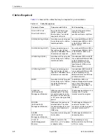
 for information.) Elsewhere 

the splitter must conform to all regional regulatory requirements.

Procedure

To cable the DSL Ports:

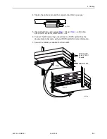
1. Insert a cable tie (provided) through the top of the anchor mount next to the 

DSL PORTS 1–24 connector.

2. If the connector for your cable has a long captive screw, attach it to the DSL 

PORTS 1–24 connector and fasten it with the captive screw.

3. If the connector for your cable has a short captive screw, install the provided 

jack screw in the threaded hole next to the DSL PORTS 1–24 connector. 
Attach the cable to the DSL PORTS 1–24 connector and fasten it to the jack 
screw with its short captive screw.

02-17082

Anchor

Mount

50-Pin

Connector

Long

Screw

Short

Screw

#4-40

Jack Screw

02-17083

Anchor

Mount

50-Pin

Connector

Summary of Contents for BitStorm 4800 Express

Page 1: ...BitStorm 4800 Installation Guide Document No 4821 A2 GN20 00 April 2002 ...

Page 2: ...ervice representative or distributor directly for any help needed For additional information concerning warranty sales service repair installation documentation training distributor locations or Paradyne worldwide office locations use one of the following methods Internet Visit the Paradyne World Wide Web site at www paradyne com Be sure to register your warranty at www paradyne com warranty Telep...

Page 3: ...nstalled in separate buildings are interconnected the voltage potential may cause a hazardous condition Consult a qualified electrical consultant to determine whether or not this phenomenon exists and if necessary implement corrective action prior to interconnecting the products 9 In addition if the equipment is to be used with telecommunications circuits take the following precautions Never insta...

Page 4: ...C before the registration number signifies that registration was performed based on a Declaration of Conformity indicating that Industry Canada technical specifications were met It does not imply that Industry Canada approved the equipment NOTICE The Ringer Equivalence Number REN for this terminal equipment is labeled on the equipment and includes the effect of the POTS splitter The REN assigned t...

Page 5: ...sure the installation of the BitStorm 4800 does not disable the alarm equipment If you have questions about what will disable alarm equipment consult your telephone company or a qualified installer Supplier s Declaration of Conformity Place of Issue Paradyne Corporation 8545 126th Avenue North Largo FL 33773 1502 USA Date of Issue 3 28 2002 Paradyne Corporation located at the above address hereby ...

Page 6: ...ct based on the standard of the Voluntary Control Council for interference by Information Technology Equipment VCCI If this equipment is used in a domestic environment radio disturbance may arise When such trouble occurs the user may be required to take corrective actions ...

Page 7: ... Desktop Installation 1 5 Mounting Brackets 1 6 Installing the Mounting Brackets for Rack Mounting 1 7 Installing the BitStorm 4800 Into a Rack 1 8 Installing the Mounting Brackets for Wall Mounting 1 10 Installing the BitStorm 4800 on a Shelf or Desktop 1 12 Installing the Management Module 1 13 2 Cabling Cabling Overview 2 1 DSL Ports 2 2 Downlink GigE Connectors 2 4 Uplink Options 2 5 Uplink Gi...

Page 8: ...he Serial Interface Type and Rate 4 5 A Connectors Cables and Pin Assignments Overview A 1 Management Port Connector A 2 Ethernet Uplink and Downlink Connectors A 3 Uplink and Downlink 8 Pin Modular Jacks A 3 Uplink and Downlink Cable Connectors A 3 DSL Network Interface Cable A 4 V 35 X 21 EIA 530 A Port A 5 EIA 530 A to X 21 Interface A 6 EIA 530 A to V 35 Interface A 8 Alarm Port A 10 Modem Por...

Page 9: ...ck Chapter 2 Cabling Describes how to install all cables for the BitStorm 4800 and Management Module Chapter 3 LEDs Explains the meaning and usage of the front panel LEDs Chapter 4 Configuration Describes the minimal configuration steps required to prepare the BitStorm 4800 for remote access Appendix A Connectors Cables and Pin Assignments Provides pinouts for all connectors on the BitStorm 4800 a...

Page 10: ... CLI and Simple Network Management Protocol SNMP to configure the BitStorm 4800 Lists and explains all CLI commands 4800 A2 GN10 BitStorm 4800 Management Module Models 4800 B1 000 and 4804 B1 000 Installation Instructions Describes how to install the 4800 and 4804 Management Modules in the BitStorm 4800 6051 A2 GZ40 BitStorm 6051 POTS Splitter Installation Instructions Describes how to install the...

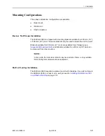
Page 11: ...nted vertically against a wall The standard mounting brackets provided can be fastened to the base of the unit for wall mounting Set on a shelf or desktop Up to eight BitStorm 4800 units may be stacked on a shelf or desktop Management Module A 4800 or 4804 Management Module must be installed in each BitStorm 4800 Power The BitStorm 4800 operates from a standard AC power supply 90 to 264 VAC at 47 ...

Page 12: ...net switch UPLINK GigE SFP Duplex modular plug and fiber optic cable Socket requires a 1000BaseX SFP transceiver not supplied A downstream BitStorm 4800 to an upstream BitStorm 4800 or the subtending or only BitStorm 4800 to the WAN via an Ethernet switch MGMT 8 position modular plug and 8 wire Category 5 or better unshielded twisted pair UTP cable The BitStorm 4800 to a Network Management System ...

Page 13: ... 4800 is shipped in a cardboard shipping container Carefully remove the unit from its shipping container and check for physical damage If the unit shows signs of shipping damage notify your sales representative Package Contents In addition to this installation guide the BitStorm 4800 shipping carton should contain BitStorm 4800 Mounting brackets one left and one right Power cord Hardware kit see T...

Page 14: ... holes 5 Dress screw 12 24 x 1 2 for use with self retaining nuts 5 Machine screw with captive starwasher 10 32 x 1 2 for use with racks with threaded holes 5 Flat head screw for attaching mounting brackets to unit 7 Jackscrew for attaching Telco connectors with short mounting screws 2 Rubber foot for desk mount and stacking of units 4 Cable tie 8 for strain relief and cable management 3 ...

Page 15: ...it to a wall Brackets suitable for a 535 mm 21 rack are available from Paradyne see Appendix B Equipment List and brackets suitable for a 610 mm 24 rack can be obtained from other sources NOTE In this guide the term rack refers to any rack cabinet frame or bay suitable for mounting telecommunications equipment Shelf or Desktop Installation The BitStorm 4800 may also be placed on a shelf or desktop...

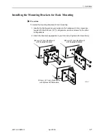
Page 16: ...ng the long side of a supplied bracket is fastened to the bottom of the unit The optional ETSI brackets are always installed with the short side fastened to the BitStorm 4800 Both the supplied brackets and the optional ETSI brackets are marked LEFT SIDE and RIGHT SIDE with reference to the left and right sides of the BitStorm 4800 when viewed from the front For wall mounting proceed to Installing ...

Page 17: ...ead screws provided in the hardware kit Six screws are required for the 483 mm 19 configuration and four screws for the other configurations 2 Attach the brackets appropriate to your rack size Tighten all screws firmly 02 17067 584 mm 23 inch Rack Mount with Supplied Brackets 483 mm 19 inch Rack Mount with Supplied Brackets 535 mm 21 1 inch Rack Mount with Optional ETSI Brackets ...

Page 18: ...ls with threaded screw holes 12 24 mounting screws and self retaining nuts for rails with unthreaded screw holes Procedure To install the BitStorm 4800 into a rack 1 Determine where in the rack you will mount the BitStorm 4800 If your rack does not have threaded screw holes slip self retaining nuts onto the rails where the BitStorm 4800 will be fastened 02 17070 ...

Page 19: ...he Management Module on page 1 13 02 17071 OK ALARM TEST 1 2 4 6 8 10 12 14 16 18 20 22 24 26 28 30 32 34 36 38 40 42 44 46 48 47 2 4 6 8 1 7 MGMT CONSOLE MODEM ALARM V 35 X 21 3 5 3 5 7 11 13 15 17 19 9 21 23 25 27 29 31 33 35 37 39 41 43 45 OK ALARM TEST 1 2 4 6 8 10 12 14 16 18 20 22 24 26 28 30 32 34 36 38 40 42 44 46 48 47 2 4 6 8 STACK POSITION 1 7 MGMT CONSOLE MODEM ALARM V 35 X 21 UPLINK G...

Page 20: ...d Procedure To install the mounting brackets for wall mounting 1 Identify the flat head screws provided in the hardware kit Two screws are required for each bracket 2 Orient the unit so that the bottom is facing you and the faceplate is at the top 3 Locate the supplied Right Side mounting bracket and fasten it to the right side of the unit 4 Locate the supplied Left Side mounting bracket and faste...

Page 21: ...e screws Leave them so their heads are about 6 mm 25 from the wall 7 Hang the unit from the wood screws to verify that the screws are properly placed The screws should freely slide into the top of the key slots in the brackets 8 Do not fasten the unit to the wall until after it is completely cabled and tested Proceed to Installing the Management Module on page 1 13 02 17147 453 mm 17 85 in ...

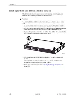
Page 22: ...Turn the BitStorm 4800 upside down on a work surface Squares stamped into the bottom of the BitStorm 4800 show the proper positions for the feet 3 Remove the protective sheet from the bottom of each foot then press the foot onto a corner of the bottom of the BitStorm 4800 4 Turn the BitStorm 4800 right side up and place it in position on a shelf or desktop If the installation includes more than on...

Page 23: ...itive components from damage due to electrostatic discharge ESD during normal operation When performing installation procedures however take proper static control precautions to prevent damage to equipment If you are not sure of the proper static control precautions contact your nearest sales or service representative Procedure To install a Management Module 1 Remove the two screws holding the slo...

Page 24: ...he faceplate of the Management Module is flush against the faceplate of the BitStorm 4800 4 Replace and fasten the two screws Do not plug in the unit Proceed to Chapter 2 Cabling OK ALARM TEST 1 2 4 6 8 10 12 14 16 18 20 22 24 26 28 30 32 34 36 38 40 42 44 46 48 47 MGMT UPLINK GigE 3 5 7 11 13 15 17 19 9 21 23 25 27 29 31 33 35 37 39 41 43 45 02 17069 ALARM V 35 X 21 4804 CONSOLE MODEM Guide Rails...

Page 25: ...e connections not all of which are required DSL Ports on page 2 2 Downlink GigE Connectors on page 2 4 Uplink ports Uplink GigE Connectors on page 2 6 V 35 X 21 Connector 4804 Management Module on page 2 7 Chaining Units Together on page 2 8 Console Port on page 2 10 Modem Port on page 2 11 Alarm Port on page 2 12 Grounding Lug on page 2 13 Power Cord on page 2 14 ...

Page 26: ...quirements Procedure To cable the DSL Ports 1 Insert a cable tie provided through the top of the anchor mount next to the DSL PORTS 1 24 connector 2 If the connector for your cable has a long captive screw attach it to the DSL PORTS 1 24 connector and fasten it with the captive screw 3 If the connector for your cable has a short captive screw install the provided jack screw in the threaded hole ne...
Page 27: ...DSL PORTS 25 48 for DSL PORTS 1 24 6 Connect the 48 tip and ring connections to a POTS splitter See the documentation that came with your POTS splitter for more information 7 Secure the cables as required for strain relief 02 17084 02 17158 DSL PORTS 1 24 DSL PORTS 25 48 UPLINK GigE DOWNLINK GigE STACK POSIT ION Front Rear POTS Splitter Card in 1 Slot Chassis BitStorm 4800 ...

Page 28: ...torm 4800 see Chaining Units Together on page 2 8 Procedure To attach an adjunct server 1 Determine the interface type to be used wire or fiber and procure the appropriate copper cable or fiber optic cable and SFP transceiver 2 For a wire connection plug the 8 position modular plug into the DOWNLINK GigE modular jack 3 For a fiber connection plug your transceiver into the DOWNLINK GigE SFP socket ...

Page 29: ...gE modular jack on the BitStorm 4800 or to a Small Form factor Pluggable SFP transceiver plugged into the UPLINK GigE SFP socket providing the appropriate interface 100BaseFX 100BaseTX 1000BaseT 1000BaseSX 1000BaseLX A CSU or router with an integral CSU connected to the V 35 X21 connector of the 4804 Management Module with an adapter or adapter cable if necessary providing the appropriate interfac...

Page 30: ...mine the interface type and procure the appropriate copper cable or fiber optic cable and SFP transceiver 2 For a wire connection plug the 8 position modular plug into the UPLINK GigE modular jack 3 For a fiber connection plug your transceiver into the UPLINK GigE SFP socket Plug your fiber optic cable into the cable socket of the transceiver 4 Connect the other end of the cable to the Ethernet sw...

Page 31: ...rews or cable ties 5 If the BitStorm 4800 is in a rack dress the cable to the left side of the rack and fasten it to the rail with cable ties 6 Connect the other end of the cable to the CSU or router Fasten the connector to the CSU or router with its captive screws or a cable tie The default interface for the BitStorm 4800 software is V 35 If you use a V 35 interface you do not need to configure t...

Page 32: ... 4 Repeat Step 2 and Step 3 until all units in the stack are cabled together In Release 1 all units must have a Management Module installed 02 17077 OK ALARM TEST 1 2 4 6 8 10 12 14 16 18 20 22 24 26 28 30 32 34 36 38 40 42 44 46 48 47 2 4 6 8 1 7 MGMT 3 5 3 5 7 11 13 15 17 19 9 21 23 25 27 29 31 33 35 37 39 41 43 45 OK ALARM TEST 1 2 4 6 8 10 12 14 16 18 20 22 24 26 28 30 32 34 36 38 40 42 44 46 ...

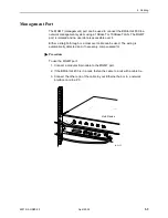
Page 33: ...s automatically detected and if necessary compensated for Procedure To use the MGMT port 1 Connect a modular 8 pin cable to the MGMT port 2 If the BitStorm 4800 is in a rack fasten the cable to a rail with a cable tie 3 Connect the other end of the cable to your Ethernet hub or to a network interface card in a PC 02 17085 OK ALARM TEST 1 2 4 6 8 10 12 14 16 18 20 22 24 26 28 30 32 34 36 38 40 42 4...

Page 34: ...ure the proper Data Terminal Equipment DTE cable type The CONSOLE port requires a DB9 plug connector The other connector depends on the serial port on your terminal or PC 3 Connect the DB9 plug connector to the CONSOLE port socket The CONSOLE port is ordinarily used only during installation so do not fasten the connector 4 Connect the other end of the cable to the serial port of your terminal or P...

Page 35: ... depends on the serial port on your modem but normally a DB25 plug is required 2 Connect the DB9 socket connector to the MODEM port socket 3 If the modem will be permanently connected fasten the connector to the Management Module with its captive screws If the BitStorm 4800 is in a rack dress the cable to the left and attach it to the rail with a cable tie 4 Connect the other end of the cable to t...

Page 36: ...M port 1 Connect a modular 8 pin cable to the ALARM port 2 If the BitStorm 4800 is in a rack dress the cable to the left and secure it to the rail with a cable tie 3 Connect the other end of the cable to your alarm monitoring system 02 17079 OK ALARM TEST 1 2 4 6 8 10 12 14 16 18 20 22 24 26 28 30 32 34 36 38 40 42 44 46 48 47 MGMT CONSOLE MODEM ALARM V 35 X 21 3 5 7 11 13 15 17 19 9 21 23 25 27 2...

Page 37: ...per ground wire 2 Loosen the screw on the grounding lug located on the back panel next to the power switch 3 Insert the stripped end of the wire through the bottom of the grounding lug and tighten the screw Ensure that the screw makes contact with the stripped portion of the wire 4 Attach the ground wire to an earth ground 02 17081 DSL PORTS 1 24 DSL PORTS 25 48 To Ground ...

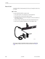
Page 38: ...the power cord into the socket under the switch 3 If the BitStorm 4800 is in a rack dress the power cord to the left and fasten it to the rail with a cable tie 4 Connect the other end of the power cord to a grounded AC power source 5 Press the On 1 position of the switch to turn on the BitStorm 4800 When power is appplied to the BitStorm 4800 the front panel Light Emitting Diodes LEDs convey the s...

Page 39: ... LEDs 02 17086 OK ALARM TEST 1 2 4 6 8 10 12 14 16 18 20 22 24 26 28 30 32 34 36 38 40 42 44 46 48 47 2 4 6 8 1 7 MGMT CONSOLE MODEM ALARM V 35 X 21 3 5 3 5 7 11 13 15 17 19 9 21 23 25 27 29 31 33 35 37 39 41 43 45 4804 UPLINK GigE DOWNLINK GigE STACK POSITI ON 25 26 27 28 29 30 31 32 33 34 35 36 37 38 39 40 41 42 43 44 45 46 47 48 MODEM CONSOLE 1 2 3 4 5 6 7 8 9 10 11 12 13 14 15 16 17 18 19 20 2...

Page 40: ...MT 1 2 3 4 5 6 7 8 OK ALARM TEST 1 2 4 6 8 10 12 14 16 18 20 22 24 26 28 30 32 34 36 38 40 42 44 46 48 47 2 4 6 8 1 7 MGMT CONSOLE MODEM ALARM V 35 X 21 3 5 3 5 7 11 13 15 17 19 9 21 23 25 27 29 31 33 35 37 39 41 43 45 4804 UPLINK GigE DOWNLINK GigE STACK POSITI ON UPLINK GigE DOWNLINK GigE STACK POSITION ...

Page 41: ...o signal is detected on the line Port has successfully trained with the remote and is active Port is attempting to train MGMT Green Off On The port is disabled or no physical connection exists A physical connection is detected OK Green Off On No power or the unit has not completed initialization Unit has power and has completed initialization STACK POSITION Green On Indicates the logical position ...

Page 42: ...itialization process Notify your service representative Off ON ON Self Test The LEDs should be in this state only during self test immediately after the unit is turned on ON Off Off Normal Operation Unit has successfully passed self test there are no alarms in the system and none of the ports is in test mode ON Off ON Test Mode At least one port is in test mode ON ON Off Alarm Unit has failed self...

Page 43: ...terface type for the V 35 X 21 port if you use an EIA 530 A or X 21 uplink Initial configuration can be performed using the Command Line Interface CLI The CLI is available from a terminal or PC connected to the CONSOLE port of the Management Module See the BitStorm 4800 User s Guide for detailed information about the CLI Conventions Used In this book the Enter key means whatever key you use to sub...

Page 44: ...he CLI then completes each word in the command For example if you enter sh man i the CLI expands it to show management ip You can obtain help with CLI commands by typing a question mark A question mark alone lists all commands A command followed by a question mark lists all usages of the command For example if you enter sh the CLI lists all the possible show commands ...

Page 45: ...and press Enter The following prompt is displayed Password 2 The default user password is null so simply press Enter The following prompt is displayed IAC IAC stands for IP Access Concentrator 3 Type privilege and press Enter to enter administrator mode The following prompt is displayed Password 4 The default administrator password is null so simply press Enter The following prompt is displayed IA...

Page 46: ...way Where address is the IP address to be assigned to the Management Module mask is the IP subnet mask for the specified address gateway is the default gateway IP address For example conf man addr 135 26 10 37 255 255 255 0 135 26 10 254 2 Press Enter The prompt changes to IAC to show that the configuration change has yet to be saved 3 Type save and press Enter 4 To verify that the address has bee...

Page 47: ...35 X 21 uplink port 1 At the IAC prompt type configure interface v35 type interface_type Where interface_type is the type of interface required by the device connected to the V 35 X 21 uplink port It must be one of eia530a v35 x21 For example conf int v35 typ x 2 Press Enter The prompt changes to IAC to show that the configuration change has yet to be saved 3 At the IAC prompt type configure inter...

Page 48: ...4 Configuration 4 6 April 2002 4821 A2 GN20 00 ...

Page 49: ... A 6 EIA 530 A to V 35 Interface on page A 8 Alarm Port on page A 10 Modem Port Connector on page A 11 Console Port Connector on page A 11 Figure A 1 BitStorm 4800 Front Panel with 4804 Management Module Figure A 2 BitStorm 4800 Rear Panel OK ALARM TEST 1 2 3 4 5 6 7 8 9 10 11 12 13 14 15 16 17 18 19 20 21 22 23 24 25 26 27 28 29 30 31 32 33 34 35 36 37 38 39 40 41 42 43 44 45 46 47 48 1 2 3 4 5 6...

Page 50: ...dular jack for a 10 100BaseT management interface Either a straight through or a crossover cable can be used The wiring is automatically detected and if necessary compensated for Table A 1 Management Port Pinouts Signal Pin Transmitted Data 1 Transmitted Data 2 Received Data 3 Unused 4 Unused 5 Received Data 6 Unused 7 Unused 8 97 15449 Pin 1 Pin 8 ...

Page 51: ...r Uplink and Downlink 8 Pin Modular Jacks The UPLINK and DOWNLINK wire connectors are 8 pin unkeyed modular jacks for 1000BaseT Uplink and Downlink Cable Connectors The UPLINK and DOWNLINK SFP sockets accept SFP transceivers compliant with the SFP Transceiver MultiSource Agreement of September 14 2000 The SFP transceivers provide cable jacks for 1000BaseLX or 1000BaseSX connections See the specifi...

Page 52: ...nnector or two connectors depending on whether the BitStorm 4800 supports 24 or 48 DSL ports respectively Table A 3 DSL Connector Pinouts lists the pin assignments for each of these interfaces Note that Pins 25 and 50 are not used Table A 3 DSL Connector Pinouts DSL Port Connector Pins Tip Ring 1 1 26 2 2 27 3 3 28 4 4 29 5 5 30 6 6 31 7 7 32 8 8 33 9 9 34 10 10 35 11 11 36 12 12 37 13 13 38 14 14...

Page 53: ...02B 23 Transmitted Data BA 103 To DSU CSU 2 A 14 B Received Data BB 104 From DSU CSU 3 A 16 B Request to Send CA 105 To DSU CSU 4 A 19 B Clear to Send CB 106 From DSU CSU 5 A 13 B Received Line Signal Detector CF 109 From DSU CSU 8 A 10 B DCE Ready CC 107 From DSU CSU 6 DTE Ready CD 108 1 2 To DSU CSU 20 Transmit Signal Element Timing DTE Source DA 113 To DSU CSU 11 B 24 A Transmit Signal Element ...

Page 54: ...ement Module provide the X 21 interface shown in Table A 5 X 21 Cable Interface Figure A 3 EIA 530 A to X 21 Adapter and Adapter Cable Pinouts 02 17090 Pin 25 Pin 1 Pin 1 Pin 15 2 14 3 16 17 9 4 19 8 10 7 24 11 2 9 4 11 6 13 3 10 5 12 8 7 14 TD A TD B RD A RD B RXC A RXC B RTS A RTS B RLSD A RLSD B SIG COMMON TT A TT B TD A TD B RD A RD B RXC A RXC B RTS A RTS B RLSD A RLSD B SIG COMMON TT A TT B ...

Page 55: ...gnal Common 102 8 Transmitted Data 103 To DSU CSU 2 A 9 B Received Data 104 From DSU CSU 4 A 11 B Request to Send 105 To DSU CSU 3 A 10 B Data Channel Received Line Signal Detector 109 From DSU CSU 5 A 12 B Transmit Signal Element Timing DTE Source 113 To DSU CSU 7 A 14 B Receiver Signal Element Timing DCE Source 115 From DSU CSU 6 A 13 B ...

Page 56: ...own in Table A 6 V 35 Cable Interface Figure A 4 EIA 530 A to V 35 Adapter and Adapter Cable Pinouts Pin 25 Pin 1 02 17088 A MM B NN 1 2 14 3 16 15 12 17 9 4 5 8 6 7 24 11 20 21 18 25 23 A P S R T Y AA V X C D F E B U W H N L NN SHIELD TD A TD B RD A RD B TXC A TXC B RXC A RXC B RTS CTS RLSD DSR SIG COMMON TT A TT B DTR RL LL TM SIG COMMON SHIELD TD A TD B RD A RD B TXC A TXC B RXC A RXC B RTS CTS...

Page 57: ...C Clear to Send 106 From DSU CSU D Data Channel Received Line Signal Detector 109 From DSU CSU F Data Set Ready 107 From DSU CSU E Data Terminal Ready 108 1 2 To DSU CSU H Transmit Signal Element Timing DTE Source 113 To DSU CSU U A W B Transmit Signal Element Timing DCE Source 114 From DSU CSU Y A AA B Receiver Signal Element Timing DCE Source 115 From DSU CSU V A X B Local Loopback 141 To DSU CS...

Page 58: ...aceplate of the 4800 or 4804 Management Module The ALARM port is an 8 pin modular connector only Pins 2 3 and 4 may be used Maximum ratings for the ALARM connector are 30 VAC 60 VDC 0 5 A Table A 7 Alarm Connector Pinouts Signal Pin None 1 Closed on Alarm Normally Open 2 Common 3 Open on Alarm Normally Closed 4 None 5 Future Use 6 Future Use 7 None 8 ...

Page 59: ...e Port Connector The CONSOLE port connector is a DB9 male connector on the faceplate of the 4800 or 4804 Management Module It supports an EIA 232 circuit as shown in Table A 9 Console Port Connector Table A 8 Modem Port Connector Signal Direction Pin Number 1 Receive Data In 2 Transmit Data Out 3 DCE Data Terminal Ready Out 4 Ground 5 Data Set Ready In 6 7 8 9 Table A 9 Console Port Connector Sign...

Page 60: ...A Connectors Cables and Pin Assignments A 12 April 2002 4821 A2 GN20 00 ...

Page 61: ... Includes BitStorm 4800 with Model 4800 B1 000 Management Module installed mounting brackets and hardware and Installation Guide 4821 A1 442 BitStorm 4800 User s Guide paper copy 4800 A2 GB20 BitStorm 6051 POTS Splitter 6051 B1 001 EIA 530 A to V 35 Adapter 4800 F1 500 EIA 530 A to V 35 Adapter Cable 4800 F1 501 EIA 530 A to X 21 Adapter 4800 F1 502 EIA 530 A to X 21 Adapter Cable 4800 F1 503 Hosp...

Page 62: ...nagement Module Includes Installation Instructions 4800 B1 000 Mounting Brackets for ETSI 535 mm 21 Rack 4800 F1 011 Splitter Block for ADSL KHZ 023 6625FF Subscriber Gateway Server 901 1011 001 Table B 1 Equipment List 2 of 2 Description Model Number ...

Page 63: ...ese are designed in accordance with IEC 60950 Electromagnetic Compatibility EMC Meets the following standards CISPR 22 Class A EN 50082 1 EN 55022 FCC Part 15 Class A VCCI Class A Network Approvals FCC Part 68 Industry Canada CS 03 DSL Compatibility The BitStorm 4800 supports G dmt G 992 1 G lite G 992 2 ANSI T1 413 1998 Installation Options The Bitstorm 4800 can be Installed on a desktop and stac...

Page 64: ...in modular jack 4804 Management Module V 35 X 21 DB25 socket EIA 530 A Operating Environment Ambient Temperature 0 to 50 C 32 to 122 F Relative Humidity 5 to 95 noncondensing Storage Temperature 40 to 70 C 40 to 158 F Shock and vibration tolerance sufficient to withstand normal shipping Physical Dimensions Height 44 0 mm 1 72 or 1U as defined in EIA 310 C without feet Width 440 0 mm 17 32 without ...

Page 65: ...E port cabling and settings 2 10 description 1 2 pin assignments A 11 cooling and air handling C 1 CSU cabling 2 7 D data rate configuring 4 5 default gateway 4 4 password 4 3 desktop installation 1 12 dimensions C 2 document purpose iii documents related iii downlink and uplink pin assignments A 3 DOWNLINK GigE ports cabling 2 4 description 1 2 pin assignments A 3 DSL PORTS cabling 2 2 descriptio...

Page 66: ...ing brackets description 1 6 positioning 1 6 mounting configurations 1 5 O operating environment C 2 optional mounting brackets 1 5 order numbers B 1 overview configuration 4 1 of book iii P package contents 1 3 part numbers B 1 password 4 3 PC cabling and settings 2 10 physical dimensions C 2 pin assignments A 1 power C 2 connecting cord 2 14 consumption C 2 requirements C 2 switch 2 14 preinstal...

Page 67: ... conventions 4 1 U unpacking 1 3 uplink configuring interface type 4 5 options 2 5 uplink and downlink pin assignments A 3 UPLINK GigE ports cabling 2 5 description 1 2 pin assignments A 3 V V 35 adapter installing 2 7 V 35 X 21 port cabling 2 7 configuring interface type and rate 4 5 description 1 2 pin assignments A 5 V 35 adapter A 8 X 21 adapter A 6 VT100 cabling and settings 2 10 W wall mount...

Page 68: ...Index IN 4 April 2002 4821 A2 GN20 00 ...

Reviews: