

Esprit and Stand-Alone Programming
The RTX3 can also be connected to an Esprit panel or function in Stand Alone mode. To enter
programming mode:
1.
Connect an Esprit 636 or 646 to the “Program” connector.
2.
Press the “Esprit Mode Programming” button.
3.
Press [
ENTER
] on your Esprit keypad and enter the installer code (default: 757575).
4.
Enter the desired section number.
When programing in Stand Alone mode, The programming sections are the same as when used with an
Esprit panel with the following exceptions:
•
In Stand Alone mode, section
[001]
, option
[1]
and option
[2]
will not affect system use
•
Panic alarms can only be used to toggle PGMs on the RTX3
•
Sections
[301]
to
[332]
do not have to be programmed
* Buttons used to arm are also used to disarm the system
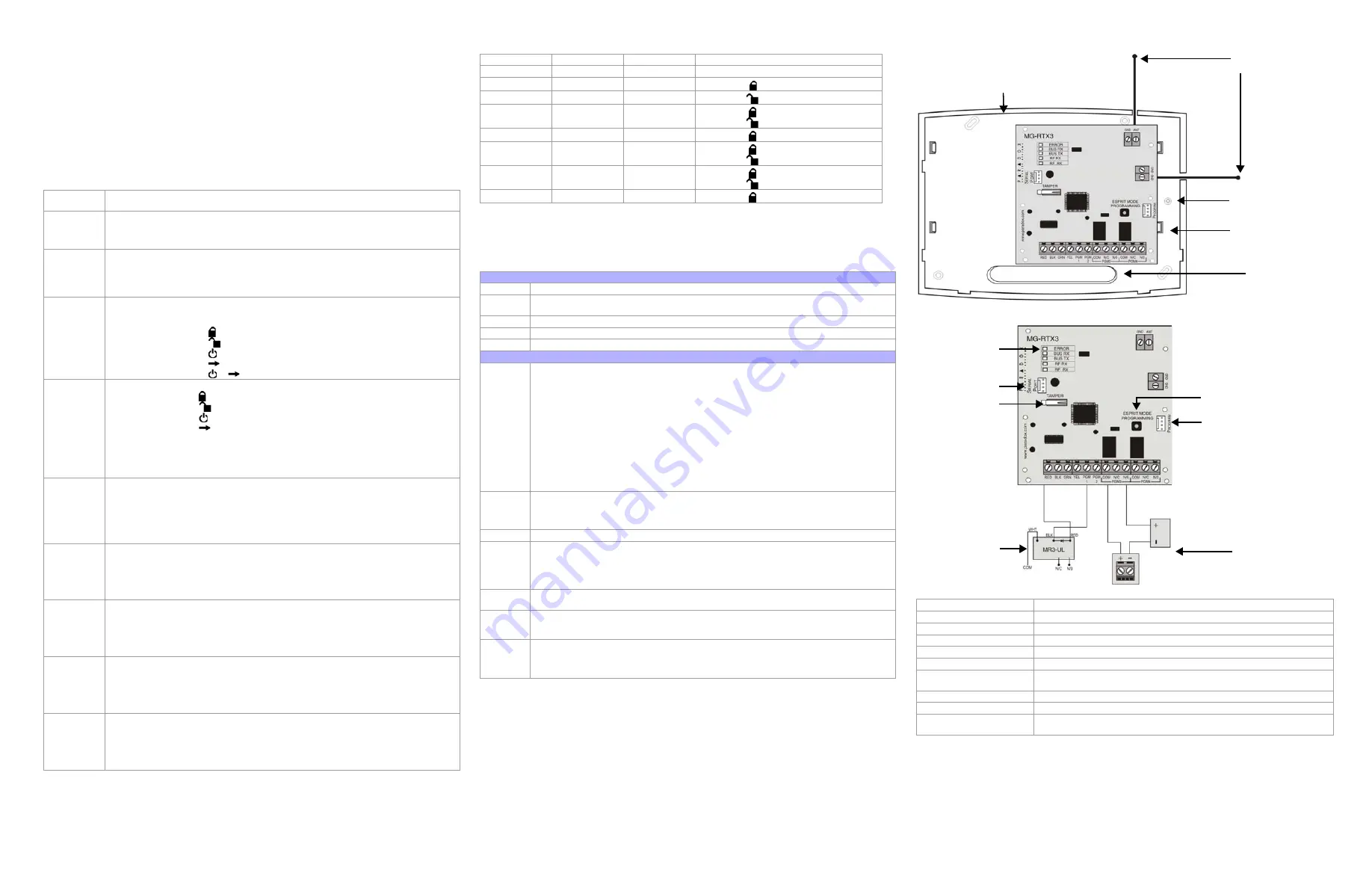
Installation Information
Figure 3: Mounting
Figure 4: PCB and Connection
Technical Specifications
Warranty
For complete warranty information on this product please refer to the Limited Warranty Statement found on the website www.paradox.com/
terms. Your use of the Paradox product signifies your acceptance of all warranty terms and conditions.
© 2008 Paradox Security Systems Ltd. All rights reserved. Specifications may change without prior notice. One or more of the following US
patents may apply: 7046142, 6215399, 6111256, 6104319, 5920259, 5886632, 5721542, 5287111, 5119069, 5077549 and RE39406 and
other pending patents may apply. Canadian and international patents may also apply.
Magellan, Digiplex, Spectra and Esprit are trademarks or registered trademarks of Paradox Security Systems Ltd. or its affiliates in Canada,
the United States and/or other countries. For the latest information on products approvals, such as UL and CE, please visit
www.paradox.com.
Table 4: Esprit / Stand Alone Programming
Section
Feature
[000]
Installer Code
Set Installer Code (4 or 6 digits, default: 757575)
[301] to [332]
User Code Assignment
Assign a valid user code from the Esprit Panel into the RTX3.
[301] = user 01; [332] = user 32.
To delete a user code, press [2ND] and then [Enter]
[201] to [232]
Remote Control Assignment
[201] = remote control 01; [232] = remote control 32
Press [Enter]. After the confirmation beep, press and hold any button on the remote until
you hear two beeps.
To delete a remote control, press [2ND] followed by [Enter].
[401] to [432]
Remote Control Button Options
[401] = remote control 01; [432] = remote control 32
Options [1] to [3]: See Table
5
.
Option [4]: Enable button for PGM activation (see section [011]) default = ON
Option [5]: Enable button
for PGM activation (see section [012]) default = ON
Option [6]: Enable button
for PGM activation (see section [013]) default = ON
Option [7]: Enable button
for PGM activation (see section [014]) default = ON
Option [8]: Enable button
+
for Panic Alarm
[011] to [014]
PGM Output Activation
[011] = Remote Button
[012] = Remote Button
[013] = Remote Button
[014] = Remote Button
Option [1]: Activate PGM 1 output (Default ON in section [011])
Option [2]: Activate PGM 2 output (Default ON in section [012])
Option [3]: Activate PGM 3 output (Default ON in section [013])
Option [4]: Activate PGM 4 output (Default ON in section [014])
Refer to section
[401]
to
[432]
[021] to [024]
PGM Latch/Delay
[021] = PGM1; [024] = PGM 4
Option [0]: Latched
Option [5]: 40 seconds
Option [1]: 1 second
Option [6]: 60 seconds
Option [2]: 5 seconds (default)
Option [7]: 2 minutes
Option [3]: 10 seconds
Option [8]: 4 minutes
Option [4]: 20 seconds
[001]
Code Length
Option [1]: ON
=
6-digit access code length (default)
OFF
=
4-digit access code length
Panic Alarm
Option [2]: ON
=
Panic Alarm toggles PGM and panic alarm. (default)
OFF
=
Panic Alarm toggles the PGM
[002]
PGM Output on Panic
Option [0]: No PGM output on panic alarm
Option [1]: Toggle PGM 1 on panic alarm
Option [2]: Toggle PGM 2 on panic alarm
Option [3]: Toggle PGM 3 on panic alarm (default)
Option [4]: Toggle PGM 4 on panic alarm
[003]
RF Lockout on Panic
Option [0]: No RF signal lockout on panic alarm (default)
Option [1]: 30-second RF signal lockout on panic alarm
Option [2]: 60-second RF signal lockout on panic alarm
Option [3]: 90-second RF signal lockout on panic alarm
Option [4]: 120-second RF signal lockout on panic alarm
[004]
Option [6]: PGM1 Initial State
OFF
=
Normally Open (default)
ON =
Normally
Closed
Option [7]: PGM2 Initial State
OFF
=
Normally Open (default)
ON =
Normally
Closed
Table 5: Remote Control Arming Options [401] to [432], Options [1] to [3]
Option
[1]
Option
[2]
Option
[3]
Definition
Off
Off
Off
No Arm or Disarm
On
Off
Off
Button
= Regular Arm
*
(default)
Off
On
Off
Button
= Regular Arm
*
On
On
Off
Button = Regular Arm
*
Button
= Regular Arm
*
Off
Off
On
Button = Force Arm
*
On
Off
On
Button = Force Arm
*
Button
= Stay Arm
*
Off
On
On
Button = Regular Arm
*
Button
= Stay Arm
*
On
On
On
Button = Stay Arm
*
Table 6: Mounting and Connection
Figure 3: Mounting
A
Back Cover
B
Antennas: The vertical antenna is the default antenna. Connect the horizontal antenna to
improve reception and range.
C
PCB Mounting Holes (x 9)
D
Mounting clip (x 4)
E
Wiring Slot
Figure 4: PCB and Connection
F
ERROR (Red):
Indicates a problem with the module.
BUS RX (Green):
Flashes when receiving information from the panel.
BUS TX (Green):
Flashes when transmitting information to the panel.
RF RX(Green):
Flashes when receiving wireless information.
RF TX(Yellow):
Flashes when transmitting wireless information.
Special Display (Digiplex EVO and Spectra SP Series only):
BUS RX
BUS TX
Error
Condition
OFF
OFF
ON
Short on GRN or YEL / Fail to Com
OFF
ON
ON
Wrong data / Invalid Combus
address (Too many modules)
ON
OFF
ON
Future Use
ON
ON
ON
Combus lines reversed
----
----
Flash
Combus power is too low
G
Connect to a 307USB and use WinLoad’s In-Field Firmware Upgrade Application to
upgrade the firmware.
Connect the PX8 to a serial port. See the PX8 installation manual for additional information.
H
Anti-Tamper Switch
I
Esprit Programming: Press to enter programming mode in Esprit mode.
System Reset: Press and hold the Programming button for 5 seconds, the BUS RX LED will
flash. Release the button and press it again while the LED flashes to reset the module to its
default values. This is only possible in the first 30 seconds after the RTX3 is powered up.
J
Connect the Esprit 636/646 LED keypad to the “Program” connector to program in Esprit
and Stand Alone mode.
K
If the current draw exceeds 150mA on PGM1 or PGM2, use a relay. Connect the RTX3’s
RED connector to the relay’s RED connector, and the PGM connector (PGM1 or PGM2) to
the relay’s BLK connector.
L
Connect PGM3 and PGM4 to external power supplies if you need additional power. A PS-
817 is recommended. Connect the PGM’s N/O connector to the external power supply’s +
connection. Connect the power supply’s - connector to the device’s - connector. Connect
the PGM’s COM connector to the device’s + connector.
DC Power
12V
DC
Frequency:
433MHz or 868MHz
Sensitivity:
-120 dBm
Current consumption:
50 mA
Dimensions (no antenna):
15cm x 16cm x 3cm (6in x 6.5in x 1.1in)
Operating temperature:
0°C to 49°C (32°F to 120°F)
PGM outputs:
PGM1 and PGM2 - 150mA PGM transistor outputs
PGM3 - form C relay output rated at 5A/28V
DC
, N.O./N.C. (PGM4 optional)
Range
Refer to the appropriate transmitter
Instructions
Other:
Di-pole antenna; Error Correction Algorithm
Approvals
For the latest information on product approvals, visit our Web site at
paradox.com
B
A
E
C
D
F
G
H
I
J
K
L


