

EVO Remote Control Programming
Use the following section to program the various remote controls in your EVO system.
It is possible to configure up to 16 different button templates, which are then assigned to individual users. Each user is pre-programmed with
a default button pattern for their remote control: (1 B) (C 0) (template 0).
Note: Button definitions and partition/one-touch definitions are linked together to create a button template. For example, Template 0 is
comprised of button definition
[2900]
together with partition/one-touch definition
[2916]
.
Remote Control Templates
To use REM3 templates:
1.
Define the 16-button definitions in sections
[2900]
to
[2915]
.
2.
Define the 16-partition/one-touch definitions in sections
[2916]
to
[2931]
.
3.
Define which button template is used as the default for remotes in section
[2940]
.
4.
Assign button templates to users in section
[2941]
.
Use the information in tables 4 and 5, as well as figure 1, to enter data in worksheet 2 and worksheet 3.
** If
0
is entered, the associated buttons will control all partitions to which the user is assigned. If
F
is entered, the associated buttons will be disabled.
REM3 Diagnostic Mode
To access the signal strength and RF activity displays (LED indicators): press and hold the Information key to unlock, then press and hold the
following three keys simultaneously: Information key (
[i]
), PGM key 1, and PGM key 2.
IMPORTANT:
Repeated use of diagnostic mode will drain the battery.
Worksheet 2: Programming remote controls
REM3 Remote Control
PGM 1
[9]
PGM 2
[0]
PGM 3
[x]
PGM 4
[
]
PGM 5
[ ]
PGM 6
[ ]
PGM 3 & 4
[x] + [
]
PGM 5 & 6
[ ] + [ ]
Default Data
1*
B*
C*
0*
5
6
0
0
Template
Section
0
[2900]
_____
_____
_____
_____
_____
_____
_____
_____
1
[2901]
_____
_____
_____
_____
_____
_____
_____
_____
2
[2902]
_____
_____
_____
_____
_____
_____
_____
_____
3
[2903]
_____
_____
_____
_____
_____
_____
_____
_____
4
[2904]
_____
_____
_____
_____
_____
_____
_____
_____
5
[2905]
_____
_____
_____
_____
_____
_____
_____
_____
6
[2906]
_____
_____
_____
_____
_____
_____
_____
_____
7
[2907]
_____
_____
_____
_____
_____
_____
_____
_____
8
[2908]
_____
_____
_____
_____
_____
_____
_____
_____
9
[2909]
_____
_____
_____
_____
_____
_____
_____
_____
10
[2910]
_____
_____
_____
_____
_____
_____
_____
_____
11
[2911]
_____
_____
_____
_____
_____
_____
_____
_____
12
[2912]
_____
_____
_____
_____
_____
_____
_____
_____
13
[2913]
_____
_____
_____
_____
_____
_____
_____
_____
14
[2914]
_____
_____
_____
_____
_____
_____
_____
_____
15
[2915]
_____
_____
_____
_____
_____
_____
_____
_____
Table 4: Template data for remote control programming
Entry
Function
K641/K641R/
K641LX
K656
0
0
Button disabled
1
1
Regular arm
2
2
Stay arm
3
3
Instant arm
4
4
Force arm
5
5
Utility key 5
6
6
Utility key 6
7
7
-
8
8
Panic 1
9
9
Panic 2
A =
STAY
A =
ARM
Panic 3
B =
FORCE
B =
SLEEP
Utility key 1
C =
ARM
C =
STAY
Utility key 2
D =
DISARM
D =
OFF
Utility key 3
E =
BYP
E =
MENU
Utility key 4
F =
MEM
F =
-
Table 5: Default template and user remote assignment
Section
Name
Description
[2940]
Default
button
template
To select a button template as the default
template, enter
00
to
15,
representing button
templates in sections
[2900]
to
[2915]
.
[2941]
Assign button
template
To assign a button template to a user, select the
user when prompted, then enter
00
to
15
,
representing button templates in sections
[2900]
to
[2915]
. If user
000
is selected, all users
are modified.
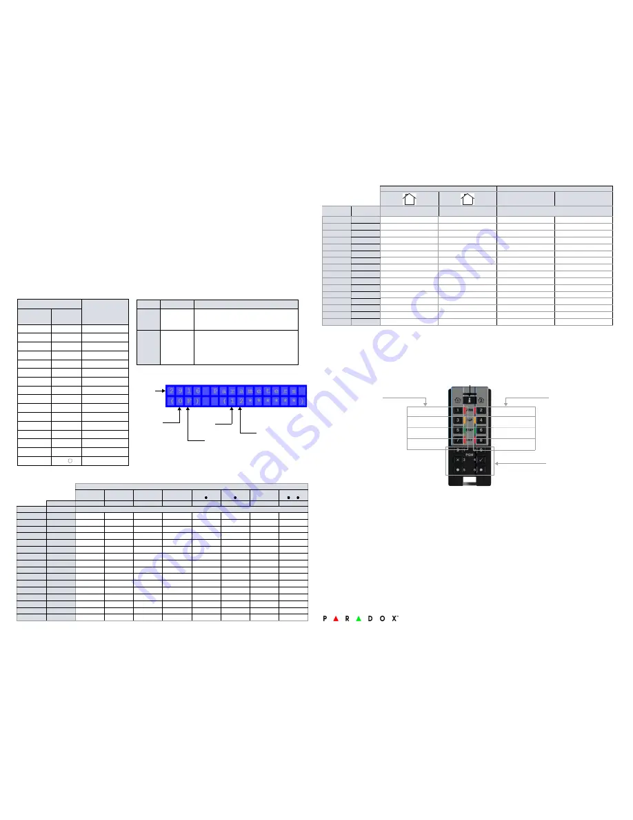
Figure 1: Entering data for section [2916] on a LCD keypad use for worksheet 2 and
worksheet 3
Section #
Default
(All User’s Partitions)
Default
(No Partitions)
One-touch
PGM Keys
One-touch
Disarm Keys
Worksheet 3: Programming remote controls continued
Partitions **
One-touch Keys
One-touch PGM Keys
One-touch Disarm Keys
Template
Section
Default = 0
(All user’s partitions)
Default = F
(No partitions)
= Disabled (default)
= Enabled
0
[2916]
_____
_____
1
[2917]
_____
_____
2
[2918]
_____
_____
3
[2919]
_____
_____
4
[2920]
_____
_____
5
[2921]
_____
_____
6
[2922]
_____
_____
7
[2923]
_____
_____
8
[2924]
_____
_____
9
[2925]
_____
_____
10
[2926]
_____
_____
11
[2927]
_____
_____
12
[2928]
_____
_____
13
[2929]
_____
_____
14
[2930]
_____
_____
15
[2931]
_____
_____
1
2
Best
Good
Acceptable
Weak
RF Interference
High RF Activity
Low RF Activity
No RF Activity
Signal Strength Display
Press
[i]
in diagnostic mode to
activate the signal strength display.
This shows the quality of the signal
received by the control panel or
RTX3. It also allows the evaluation of
a site before the installation of any
wireless transmitter. For example,
place the REM3 where you intend to
install a wireless door contact to see
the quality of the signal strength.
RF Activity
This shows the amount of RF
activity found on the same
frequency as the REM3. If the
four LEDs stay lit up, RF
interference has been
detected. This can be used to
confirm the presence of RF
interference before
installation.
Information Key
PGM Keys
Warranty
Patents
: One or more of the following US patents may apply: 7046142, 6215399, 6111256, 6104319, 5920259, 5886632, 5721542, 5287111, and RE39406. Other pending
patents, as well as Canadian and international patents may also apply.
Trademarks
: Magellan and Digiplex EVO are trademarks of Paradox Ltd. or its affiliates in Canada, the United States and/or other countries.
Certification
: For the latest information on products approvals, such as UL and CE, please visit
paradox.com
.
Warranty
: For complete warranty information on this product please refer to the Limited Warranty Statement found on the website www.paradox.com/terms. Your use of the
Paradox product signifies your acceptance of all warranty terms and conditions.
© 2013 Paradox Ltd. All rights reserved. Specifications may change without prior notice.


