background image

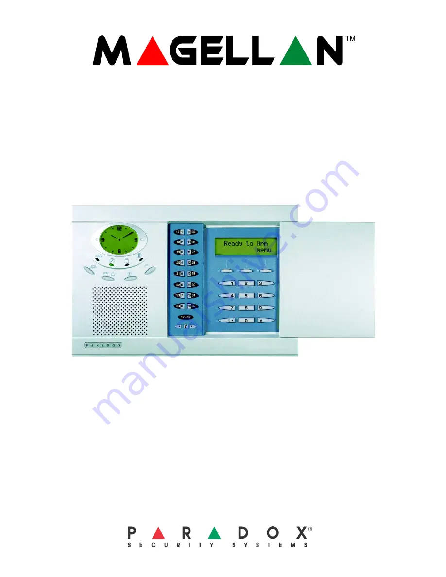
All-In-One Wireless Security System V2.0

Model #: MG-6130 / MG-6160

Reference and Installation Manual

We hope this product performs to your complete satisfaction. Should you have any questions or comments, please visit 

www.paradox.com and send us your comments.

Summary of Contents for MG-6130

Page 1: ...ty System V2 0 Model MG 6130 MG 6160 Reference and Installation Manual We hope this product performs to your complete satisfaction Should you have any questions or comments please visit www paradox com and send us your comments ...

Page 2: ......

Page 3: ...es to Stay Arming 22 Regular Arming Switches to Force Arming 22 Stay Arming Switches to Force Arming 22 Timed Auto Arming 22 No Movement Auto Arming 22 Auto Arming Options 23 One Touch Arming 23 Exit Delay 23 Bell Squawk on Arm Disarm with Remote Control 23 No Exit Delay when Arming with Remote Control 23 Exit Delay Termination 23 Follow Zone Switches to Entry Delay 2 23 Closing Delinquency Timer ...

Page 4: ...er Supervision 36 Console Audible Trouble Warning 36 FM Tuner Option MG 6160 only 36 Daylight Savings Time 36 AC Power Failure Warning 36 The Trouble Display 36 WinLoad Software Settings 38 Panel Answer Options 38 Panel Identifier 38 PC Password 38 PC Telephone Number 38 Call Back Feature 38 Appendix 1 Automatic Report Code List 39 Appendix 2 Ademco Contact ID Report Code List 41 Index 44 ...

Page 5: ...max for UL installations Auxiliary output When using an AC or DC power source the auxiliary output provides 13 8V 200mA maximum To achieve this value use a minimum of 15Vdc Backup Battery 7 2Vdc 1 8Ah NiMH rechargeable battery pack order 0780100178 Not user replaceable Replace battery every 3 5 years PGM1 N O solid state relay not polarized Internal resistance 16 9max Max handling current 100mA PG...

Page 6: ...you see the Zone Profile menu or press the 6 key to immediately access the Zone Profile menu For more in depth programming of the console s communication features see Reporting and Dialer Settings on page 27 4 Adding and Programming Zones 1 From the Zone Profile menu press OK 2 Select which zone you wish to add by pressing NEXT and press OK when the desired zone number appears 3 Press the tamper s...

Page 7: ...pear Press EXIT For more in depth programming of the console s passwords see User Codes on page 14 and WinLoad Software Settings on page 38 8 Time and Date 1 Press the MENU key 2 Press NEXT until you reach the Time and Date menu and press OK or press the 3 key to access the Time and Date menu 3 Select the time format 12Hr clock or 24Hr clock and then program the time Press OK when done Program the...

Page 8: ...ou wish to assign to the selected zone When you complete an output programming option you will be given the choice to configure another output If you do not choose to program another output you will be brought back to the Output Profile menu Deleting Outputs 1 From the Output Profile menu press OK 2 Select which output you wish to delete by pressing NEXT and then OK when the desired output number ...

Page 9: ... on page 7 Connect the backup battery pack after applying AC power Figure 3 Connecting the Backup Battery To order a battery pack the battery pack s part number is Paradox 0780100178 The backup battery can support Magellan during an AC failure for 24 hours when in standby mode Auxiliary Output The auxiliary power supply terminals can be used to power motion detectors The combined current consumpti...

Page 10: ...for more information on connecting the telephone line using this method When connecting via the LINE plug if the telephone line is shared and it is busy i e someone is talking on the telephone the console will be unable to communicate with the Monitoring Station It is recommended that the Direct Connect method see page 8 be used to connect the telephone line Figure 6 Line Plug Connection Programma...

Page 11: ... two on board hardwire zones See Zones 31 and 32 Become Hardwire Zones on page 18 for more information After connecting the detection devices the zones must be defined See Zone Programming on page 15 for more information The hardwire zones follow the console s EOL and tamper definitions Though any hardwire detection device can be connected to Magellan s on board hardwire zone inputs it is recommen...

Page 12: ...rd household electrical wiring using X10 transmitters and receivers Configure Magellan with the use of an X10 transmitter to automate a home Connect the X10 transmitter as shown in Figure 12 on page 10 Refer to the Magellan X10 Instructions on our website paradox com for information on using and configuring Magellan s X10 feature Figure 12 Connecting the X10 Transmitter The X10 feature is not for ...

Page 13: ...nstalled below ground level However if it is absolutely necessary to install the console in the basement install the console as high as possible Install the Magellan console on a wall allowing at least 5cm 2 around the console to permit adequate ventilation and heat dissipation The Wall Plate Magellan uses a plastic wall plate to stay mounted on a wall The wall plate is also used for tabletop moun...

Page 14: ...nst the wall plate 2 Slide the Magellan s open slots labeled D see Figure 16 on page 11 onto the wall plate s tabs labeled B see Figure 15 on page 11 3 Gently apply downward pressure to insert the wall plate s tabs into Magellan s open slots 4 Insert two screws through the wall plate s screw holes labeled C and into holes labeled E see Figure 16 on page 11 in the Magellan back plate 5 Attach the p...

Page 15: ...on s options are set When the options are set press the key to save and advance to the next section Press the key twice to exit without changing any data Programming Using a Paradox Memory Key The Paradox Memory Keys PMC 3 are very useful when multiple Magellan consoles are to be programmed identically Rather then programming each console by entering its programming mode and then scrolling through...

Page 16: ...to program all features options and commands except for the console s communication settings sections 108 to 112 and 180 to 182 as well as any User code The Maintenance code can be 4 or 6 digits in length see User Code Length on page 14 Each digit can be any value from 0 to 9 To change the Maintenance code 1 Access the installer programming mode see page 13 2 Enter section 182 3 Enter a new 4 OR 6...

Page 17: ...on page 15 except it uses a separate Entry Delay Timer Entry Delay 2 Timer Section 061 001 to 255 seconds 000 Disabled Default 45 seconds Enter the desired 3 digit delay value from 000 to 255 seconds into section 061 to program the Entry Delay 2 Timer Follow Zones Sections 001 to 032 Zones 1 to 32 3 digit 003 When an armed Follow zone opens the console will immediately generate an alarm unless an ...

Page 18: ...on page 16 Figure 20 Bell Siren Output during a Fire Alarm Delayed Fire Zones Sections 001 to 032 Zones 1 to 32 3 digit 008 When a Delayed 24Hr Fire zone opens whether it is armed or disarmed the console will react as shown in Figure 21 on page 16 Delayed 24Hr Fire zones are commonly used in residential homes where a smoke detector often generates false alarms i e burning bread etc This feature is...

Page 19: ...one Shutdown Counter Section 067 001 to 015 alarms 000 Disabled Default 5 alarms Enter the desired limit into section 067 to program the Auto zone Shutdown Counter Bypass Option Section 001 to 032 Zones 1 to 32 Option 2 Option 2 OFF Bypass option disabled Option 2 ON Selected zone is Bypass enabled default When a user uses the Bypass Programming feature only zones with the Bypass option enabled ca...

Page 20: ...led default Option 1 ON Stay Delay zone enabled When a Follow Stay or Instant Stay zone is armed using the Stay or Instant arming methods with this option enabled and the zone is triggered an alarm will not generate until the programmed Stay Delay elapses A zone defined as Stay Delay follows the Entry Delay 1 Timer To program the Entry Delay Timers refer to Entry Delay 1 on page 15 This feature is...

Page 21: ...oorbell Tones Section 096 Options 1 to 4 Options 1 and 2 Set tone for wireless doorbell 1 Options 3 and 4 Set tone for wireless doorbell 2 Section 096 options 1 to 4 set the tones that will be played when Magellan receives a signal from either wireless doorbell 1 or 2 or both Magellan comes with four tones Refer to Table 3 on page 19 to set the desired tone Table 3 Wireless Doorbell Tones Deleting...

Page 22: ...ler programming mode see page 13 2 Enter the SECTION sections 041 to 056 corresponding to the desired remote control 3 Enter the HEXADECIMAL VALUE 0 to F of the desired button option from the Button Options Table on page 23 If you do not wish to program all the buttons or button combinations press the key at any time to save and exit If you enable any Panic button options you must enable the Panic...

Page 23: ...sign a wireless repeater 1 Access the installer programming mode see page 13 2 Enter the SECTION corresponding to the desired repeater 3 Enter the 6 digit SERIAL NUMBER of the wireless repeater Wireless Repeater Options Section 300 to 305 Options 1 to 8 Repeater 1 options Section 306 to 311 Options 1 to 8 Repeater 2 options Defaults OFF Sections 300 to 303 represent zone repeating options for Repe...

Page 24: ...o arming can be cancelled by entering a valid Access code Once the system has successfully armed the console can transmit the Timed Auto Arming report code programmed in section 124 Example To automatically arm the system everyday at 6 15PM enable section 092 option 1 to activate Timed Auto arming and then key in 18 15 into section 085 This feature is not for use in UL installations Auto arm Timer...

Page 25: ...Delay Termination Section 093 Option 6 Option 6 OFF Exit Delay Termination disabled Option 6 ON Exit Delay Termination enabled default When option 6 is enabled ON the console will reduce the Exit Delay to 10 seconds when an Entry Delay zone see Exit Delay on page 23 is opened and closed during the Exit Delay Example 15 seconds into a 45 second Exit Delay an Entry Delay zone opens and closes The re...

Page 26: ...me period Magellan can generate a trouble an alarm and or transmit a report code to the monitoring station as defined by the Wireless Transmitter Supervision Options see page 24 Sections 190 and 193 determine which zones will be supervised and which will not Enable the option pertaining to the zone you wish Magellan to supervise This feature must be enabled in UL installations Check in Supervision...

Page 27: ...eaters to send a status signal within a specified time see Check in Supervision Time on page 24 to confirm their presence and functionality If a device has not sent a signal within the specified time period or Magellan tries to communicate with the device without success Magellan can generate a trouble an alarm and or transmit a report code to the monitoring station as defined by the Wireless Tran...

Page 28: ...erate panic alarms Panic Alarm Types Section 091 Options 4 5 and 6 Option 4 OFF Panic 1 Non Medical Emergency Panic is silent default Option 4 ON Panic 1 Non Medical Emergency Panic is audible Option 5 OFF Panic 2 Auxiliary Panic is silent default Option 5 ON Panic 2 Auxiliary Panic is audible Option 6 OFF Panic 3 Fire Panic is silent default Option 6 ON Panic 3 Fire Panic is pulsed Options 4 to 6...

Page 29: ...rming The system was armed using a One touch Arming feature see page 23 Arming via PC The system was armed using the WinLoad software Disarming Report Codes Sections 126 to 129 A report code can be programmed for each of the 16 User codes Whenever an Access code is used to disarm the system or an alarm the Magellan console can send the appropriate report code to the monitoring station identifying ...

Page 30: ...tempts to communicate with the monitoring station The report code will be transmitted upon the next successful attempt Wireless Low Battery The battery voltage of a wireless transmitter motion detector or contact switch has dropped below recommended limits Tx Supervision Loss Check in Supervision see page 24 has been enabled and a transmitter is no longer communicating with the system Section 167 ...

Page 31: ...ers are used please refer to Event Call Direction on page 31 and Reporting Formats on page 30 Also refer to Delay Between Dialing Attempts on page 31 For UL installations the number of dialing attempts shall not exceed 10 MSTN 2 as Backup Number Section 099 Option 1 Option 1 OFF Use MSTN 2 as a monitoring station telephone number only Option 1 ON MSTN 2 can be used a backup telephone number defaul...

Page 32: ...ole 1 Press MENU and then press the 4 key 2 Enter the INSTALLER CODE and then press the 3 key 3 Press NEXT until the Utility Reporting screen appears then press OK 4 Press NEXT until the desired telephone number appears then press OK 5 Enter the desired telephone number and then press OK twice 6 Press NEXT until the desired report type appears then press OK see Report Types on page 30 7 Press NEXT...

Page 33: ...tion 2 ON Call MSTN 2 Option 3 ON Call Pager telephone number The events are divided into five groups see above where each event group can be programmed to dial up to three telephone numbers MSTN 1 2 and the Pager telephone number with one as a possible backup see MSTN 2 as Backup Number on page 29 When a reportable event occurs in the system the Magellan console will begin dialing the numbers seq...

Page 34: ... settings below These will be restored when the console detects the telephone line again Table 9 Telephone Line Monitoring Options Please note that when the dialer detects an incoming call the TLM test will stop for 1 minute If transmission is used off premises telephone line monitoring must be used in UL installations TLM Fail Timer Section 073 001 to 255 seconds 000 Disabled Default 32 seconds I...

Page 35: ...llowing an alarm Zone Restore Report Options Section 094 Option 2 Option 2 OFF Report on Bell Cut Off default Option 2 ON Report on zone closure With option 2 OFF the Magellan console will send the Zone Alarm Restore report codes see page 27 to the monitoring station when the zone has returned to normal and the Bell Cut Off Timer see page 24 has elapsed With option 2 ON the console will send the Z...

Page 36: ...GM Activation Event on page 34 Wireless PGM Activation Event on page 35 Onboard PGM Deactivation Event on page 34 and Wireless PGM Deactivation Event on page 35 If both PGM1 and PGM2 are set as hardwire onboard Magellan will ignore sections 260 to 267 and 280 to 283 Onboard PGM Activation Event Section 086 PGM1 Activation Event Section 088 PGM2 Activation Event This feature allows you to program t...

Page 37: ...ation Event 1 Enter the section that corresponds to the desired wireless PGM Wireless PGM1 260 Wireless PGM2 262 Wireless PGM3 264 Wireless PGM3 266 2 Enter the EVENT GROUP 3 Enter the SUB GROUP The AC Loss PGM event Event Group 28 Event Sub group 01 will only occur after the Power Failure Report Delay elapses see page 33 For the Event List see the PGM Table in the Magellan Programming Guide Wirel...

Page 38: ...ed With section 093 option 8 ON the Magellan s radio is turned ON automatically after the system is armed after the Exit Delay Timer has elapsed Daylight Savings Time Section 096 Option 5 Option 5 OFF Daylight Savings Time disabled default Option 5 ON Daylight Savings Time enabled With section 096 option 5 ON Magellan adjusts the system s clock time for daylight savings changes At 2 00AM on the fi...

Page 39: ...have not sent a check in signal within the programmed interval see page 24 Console Tamper The Magellan console was tampered with Zone Tamper Zone s and or wireless output s displayed was were tampered with Fail to Communicate with Central The Magellan console has failed to contact the monitoring station Fail to Communicate with Voice Reporting The Magellan console has failed to contact telephone n...

Page 40: ...onsole will answer the call You must wait at least 10 seconds before attempting the second call or Magellan will think it is the same call Panel Identifier Section 108 4 digit Hexadecimal number from 0000 to FFFF This 4 digit code identifies the console to WinLoad before initiating communication Magellan will verify that the Panel Identifier in the WinLoad software is the same as the code programm...

Page 41: ...pen by user OR Disarm from Alarm Cancel alarm with User Code 1 4A6 Open by user OR Disarm from Alarm Cancel alarm with Keyswitch 1 4A6 Keyswitch Open OS Opening Keyswitch Auto Arming Cancellation 1 4A5 Deferred Open Close CE Closing Extend Disarm with PC software 1 4A7 Remote arm disarm OP Opening Report Disarm after an alarm with PC software 1 4A7 Remote arm disarm OR Disarm From Alarm Quick disa...

Page 42: ...YT System Battery Trouble Module Auxiliary supply trouble 1 3AA System trouble YP Power Supply Trouble Bus fault restore 3 333 Expansion module failure restore ER Expansion Restoral Module tamper restore 3 145 Expansion module tamper restore TR Tamper Restoral Module ROM_RAM_error restore 3 3A4 Rom checksum bad restore YG Parameter Changed Module TLM restore 3 352 Telco 2 fault restore LR Phone Li...

Page 43: ...igeration 27 153 Loss of heat 28 CID Reporting Code Programming Value 154 Water leakage 29 155 Foil break 2A 156 Day trouble 2B 157 Low bottled gas level 2C 158 High temperature 2D 159 Low temperature 2E 161 Loss of air flow 2F 162 Carbon monoxide detected 30 163 Tank level 31 Fire Supervisory 200 and 210 200 Fire supervisory 32 201 Low water pressure 33 202 Low CO2 34 203 Gate valve sensor 35 204...

Page 44: ...intenance alert 7A Open Close 400 400 Open Close 7B 401 Open Close by user 7C 402 Group open close 7D 403 Automatic open close 7E 406 Cancel 7F 407 Remote arm disarm 80 CID Reporting Code Programming Value 408 Quick arm 81 409 Keyswitch open close 82 Remote Access 410 411 Call back request made 83 412 Success download access 84 413 Unsuccessful access 85 414 System shutdown 86 415 Dialer shutdown ...

Page 45: ...rigger test BD 602 Periodic test report BE 603 Periodic RF transmission BF 604 Fire test C0 605 Status report to follow C1 606 Listen in to follow C2 607 Walk test mode C3 608 Periodic test system trouble present C4 609 Video transmitter active C5 611 Point test OK C6 612 Point not tested C7 613 Intrusion zone walk tested C8 614 Fire zone walk tested C9 615 Panic zone walk tested CA 616 Service re...

Page 46: ... 29 114 29 115 38 116 30 119 30 120 to 123 27 124 22 27 125 27 126 to 129 27 130 27 131 to 134 27 135 to 138 27 139 27 140 14 27 28 141 to 144 28 145 to 148 28 149 28 150 28 29 151 28 29 154 28 29 155 28 161 to 176 20 173 28 174 28 29 175 29 176 29 180 36 181 14 182 14 187 16 190 16 200 14 201 19 36 210 35 211 35 212 35 213 35 214 35 215 35 216 35 217 35 218 25 232 19 233 19 234 19 240 35 241 35 2...

Page 47: ... Auxiliary 7 B Backup Alarm Reporting Option 25 Backup telephone number 29 Battery pack 7 Bell Cut off timer 24 Bell squawk on Arm Disarm with Remote Control 23 Bypass option 17 Bypass options Supervision 24 Bypass options Tamper 25 C Call back feature 38 Call direction 31 Central station telephone numbers 29 Check in Supervision time 24 Closing Delinquency Timer 23 Code length 14 Codes Code lengt...

Page 48: ...tion 31 Force Zones 18 Formats reporting 30 H Hardwire zone connections 9 I Indentifier panel 38 Installer code 14 Installler lock 36 Instant Zones 16 Instant Stay Zones 16 Intellizone 17 Intellizone Delay timer 18 L Line plug connect 8 Location 11 Lock system master code 14 Lock installer 36 M Maintenance code 14 Master code 14 Master code lock 14 Master code reset 14 Memory Key 10 Memory Key pro...

Page 49: ...ts 30 Switch to Pulse dialing 32 TLM 32 Zone Restore Report options 33 Reset software 36 Reset system master code 14 RF Interference Detection 33 RF Jamming Supervision 33 S Service telephone number 30 SESCOA 30 Setting PGM 1 PGM2 Function 34 Shutdown Auto zone 17 SIA FSK 31 Silent Knight Fast 30 Single digit data entry method 13 Software reset 36 Special alarm report codes 27 Special arming repor...

Page 50: ... Delay 35 Wireless PGM Supervision Options 25 Wireless programmable outputs Activation event 35 Deactivation event 35 Wireless programming Assigning remote controls 20 Assigning wireless doorbells 19 Assigning wireless zones 19 34 Deleting wireless zones 19 Programming remote control buttons 20 Viewing signal strength 19 Wireless Repeater Supervision Options 21 25 Wireless Transmitter Supervision ...

Page 51: ...ed In most but not all areas sum of the ren s of all devices connected to one line should not exceed five 5 0 To be certain of the number of devices that you may connect to your line you may want to contact your local telephone company EQUIPMENT MAINTENANCE FACILITY If you experience trouble with this telephone equipment please contact facility indicated below for information on obtaining service ...

Page 52: ...pport in Canada or the U S call 1 800 791 1919 Monday to Friday from 8 00 a m to 8 00 p m EST For technical support outside Canada and the U S call 00 1 450 491 7444 Monday to Friday from 8 00 a m to 8 00 p m EST Please feel free to visit our website at www paradox com ...

Reviews: