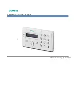
Keypad Description
Each keypad/repeater (Figure 1) has several buttons with some having dif-
ferent functions depending on the system’s state.
Figure 1.
SmartX Stand Alone LCD Keypad/Repeater
For keys’ functionality please refer to the SmartX User Manual.
BUS Connection
If the system has more keypads/repeaters other than the one inside the
main cabinet, they must be connected with the 4 wire bus. Each keypad/
repeater has a 4 way terminal block for this purpose. The correct connec-
tion is show in Figure 2. Take great care not to mix the data wires with the
power wires as permanent damage may be caused. Additional 7 keypads/
repeaters can be connected.
B
+
-
A
MAIN BOARD
Stand Alone LCD
Keypad/Repeater
GND
Vbus A
Next keypad/
Repeater
-
Figure 2.
BUS connection
Setting keypads/repeaters IDs
1 2 3 4
SW1
ON
Figure 3.
Set of dip switches
It is very important to set a unique address to each keypad/repeater. Follow
the rules below to set a correct set of addresses:
Micro switches SW1
ID
SW1-4
SW1-3
SW1-2
SW1-1
1
OFF
OFF
OFF
ON
2
OFF
OFF
ON
OFF
3
OFF
OFF
ON
ON
4
OFF
ON
OFF
OFF
5
OFF
ON
OFF
ON
6
OFF
ON
ON
OFF
7
OFF
ON
ON
ON
Table 1.
Keypads’ micro switches SW1 ID settings


