


9
0
1
2
3
4
5
6
1/2
1/2
1/2
1/2
1/2
1/2
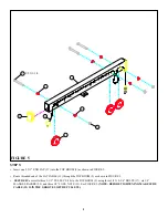
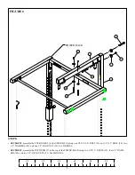
STEP 6:
FIGURE 6
•
SECURELY
assemble the TOP BOOM (2) to the UPRIGHT (1) using one 1/2 X 2-3/4” BOLT (23), one 1/2 X 3” BOLT (24), two
1/2” WASHERS (25), and one 1/2” LOCK NUT (26). See FIGURE 6.
•
SECURELY
assemble the TOP BOOM (2) to the top of the POWER RACK using two 3/8 X 3” BOLTS (18), four 3/8” WASH-
ERS (20), and two 3/8” LOCK NUTS (21). See FIGURE 6.
POWER RACK
21
2
23
20
1
25
26
18
24


