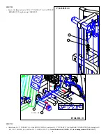
ParaBody 441101 440 Assembly Instructions Manual Download Page 7

7

STEP 9

Install the 

NEW

 110-3/4” CABLE ASSY (16) using the following steps:

•   Route the CABLE (16) back over one pulley in the TOP BOOM, down through the PULLEY BRACKET (2) and over the second

pulley in the TOP BOOM.

•   Route the CABLE (16) around the PULLEY BLOCK as shown in FIGURE 9.

•   Route the CABLE (16) through the TOP BOOM as shown in FIGURE 9. The pulleys in TOP BOOM may need to be temporarily

removed to perform this step. 

(Note: Make sure the CABLE is running OVER the BOLTS connecting the FRONT UPRIGHT

to the TOP BOOM. These may also have to be removed to perform this step.)

    FIGURE 9

 2

16

    FIGURE 10

3/8 X 1-3/4”  13

16

11

 2

STEP 10

•   Loop CABLE (16) around one 3-1/2” PULLEY (5) in the PULLEY

BRACKET (2) using one 3/8 X 1-3/4” BOLT (13) and one 3/8”
LOCKNUT (11) as shown in FIGURE 10.

 5

•   Screw the threaded end of CABLE (16) into the HEAD PLATE

ASSEMBLY.

IMPORTANT: Cable must run over the top of
bolts.

Summary of Contents for 441101 440

Page 1: ...441101 440 LEG PRESS ADAPTER KIT Part 7039101 REV B Revision 07 19 01 1 ASSEMBLY INSTRUCTIONS WARNING Read and follow all directions for each step to insure proper assembly of this product...

Page 2: ...ustable wrench Tape measure 2 NOTE BOLT LENGTH IS MEASURED FROM THE UNDERSIDE OF THE HEAD OF THE BOLT BOLT LENGTH RULER 3 Do not allow minors or children to play on or around this equipment 2 Inspect...

Page 3: ...T 3 8 X 3 BOLT 1 2 X 3 1 4 BOLT 110 3 4 CABLE ASSY 82 1 2 CABLE ASSY QTY 4 5 2 3 2 2 1 1 DESCRIPTION FRONT LEG PULLEY BRACKET CABLE SWIVEL BASE CONNECTION 3 1 2 PULLEY 2 SQ END CAP COVER CAP QUICK DIS...

Page 4: ...and two 1 2 LOCKNUTS 12 See FIGURE 4 STEP 5 Remove one existing 3 1 2 PULLEY and two SPACERS from theADJUSTMENT TUBE on the 100 LEG PRESS OPTION by unfastening the 3 8 X 4 1 2 BOLT holding the pulley...

Page 5: ...WASHERS 2 WHEELS AND NUT Note Securely tighten then back off 1 4 turn to allow the CABLE SWIVEL WHEELS to rotate freely See FIGURE 6 5 2 WHEEL 3 8 X 4 1 2 BOLT NUT 2 WHEEL STEP 7 Securely fasten the 1...

Page 6: ...the threaded end of CABLE from the HEAD PLATE ASSEMBLY Route the LAT CABLE around the PULLEY BLOCK as shown in FIGURE 8 REMOVE CABLE FIGURE 8 The pulleys in TOP BOOM may need to be temporarily removed...

Page 7: ...pulleys in TOP BOOM may need to be temporarily removed to perform this step Note Make sure the CABLE is running OVER the BOLTS connecting the FRONT UPRIGHT to the TOP BOOM These may also have to be r...

Page 8: ...LE SWIVEL 3 with one QUICK DISCONNECT LINK 8 IMPORTANT Tighten the QUICK DISCONNECT LINK 8 securely 8 0 1 2 3 4 5 6 1 2 1 2 1 2 1 2 1 2 1 2 Route the 82 1 2 CABLE 17 under the WEIGHT STACK as shown in...

Page 9: ...PULLEY BRACKET 2 as shown in FIGURE 12 STEP 13 Attach one 3 1 2 PULLEY 5 to the FRONT LEG 1 and one 3 1 2 PULLEY 5 to the BASE CONNECTION 4 using two 3 8 X 1 3 4 BOLTS 13 and two 3 8 LOCKNUTS 11 Note...

Page 10: ...IGHT STACK PIN Thread the 110 3 4 CABLE 16 into the HEAD PLATE ASSEMBLY until the PULLEY BRACKET 2 is held against the TOP BOOM and the cable is slightly pulling up on the HEAD PLATE Tighten the jan b...

Reviews: